
The Science of the Plateau: Why Voltage Stability is the Lifeline of in Power System
Voltage Stability is the ability of a battery-powered system to keep its working voltage inside the electronics’ safe range during steady drain, short peak pulses, and cold starts.
The voltage stability depends on the cell, the load profile, and the power path[1] inside the product. Strong stability reduces brownouts[2], protects data integrity, and lowers service risk.
A remote device can run for years and fail in one second when its supply sags during a burst. That failure wastes time because it looks random in the field.
When a team treats voltage stability as a design target, the reset becomes measurable and preventable.
Stay with me, because the plateau is not only chemistry. It is also system design.
Quick FAQ Review About Voltage Stability(Click to Unfold)
Q: What is meant by voltage stability?
A: Voltage stability refers to a power system’s ability to maintain acceptable voltage levels under normal operation and after disturbances.
Q: What are the three types of voltages?
A: The three main types are nominal voltage, operating voltage, and maximum/minimum allowable voltage.
Q: How to check if voltage is stable?
A: Voltage stability is checked by monitoring voltage levels over time and ensuring they stay within defined limits under varying loads.
Q: How to keep voltage stable?
A: Voltage can be kept stable using proper power system design, voltage regulators[3], energy storage devices, and load management.
Q: What are the symptoms of voltage collapse?
A: Common symptoms include rapid voltage drop, equipment malfunction, communication failure, and system blackout.
Q: What is the criteria for voltage stability?
A: A system is considered voltage stable if it can supply increasing load demand without voltage dropping below safe thresholds.
Q: How to measure voltage stability?
A: Voltage stability is measured using voltage margin analysis[4], load flow studies, and real-time voltage monitoring tools[5].
Q: How to fix unstable voltage?
A: Unstable voltage can be fixed by upgrading power capacity, improving wiring, adding voltage regulation, or using batteries and supercapacitors.
Q: What is long-term voltage stability?
A: Long-term voltage stability focuses on maintaining stable voltage over extended periods considering load growth and temperature effects.
Table of Contents
- What creates a voltage plateau in primary lithium systems?
- How do pulse loads erode real voltage margin?
- How do temperature and aging shift what the device actually sees?
- Which system steps keep long-life devices stable in the field?
What creates a voltage plateau in primary lithium systems?
A plateau forms when the cell’s dominant reactions proceed steadily, so terminal voltage stays near a narrow band for much of the usable capacity.

The plateau shape is set by chemistry, electrode design, and current draw. It is reliable only when it is measured under a realistic duty cycle.
A plateau supports predictable power rails, which is why Voltage Stability matters in industrial meters and safety devices.
It also sets the baseline for Voltage Stability checks in qualification. Still, a flat-looking datasheet line is not enough. Your design must account for short peaks, wiring losses, and how the cell behaves after storage.
Chemistry sets the baseline, but duty cycle[6] sets reality
Many long-life products choose a lithium thionyl chloride cell(LiSOCl2) and lithium manganese dioxide cell(LiMnO2), because it can support long service intervals and low self-discharge.
In practice, the key question is not only “How long is the plateau?” The key question is “How stable is it under my load pattern?” A product that sleeps for hours and then transmits can stress the supply in a way that a constant-drain graph does not show.
This is why a qualification plan should include storage recovery checks and duty-cycle tests that match the device’s real rhythm.
Plateau Drivers You Should Validate
| Driver | What it changes | What to test |
|---|---|---|
| Chemistry selection | Nominal voltage and plateau length | Steady drain at expected temperature |
| Electrode design | Polarization under load | Peak-pulse sag at the load pin |
| Storage history | First-burst recovery behavior | Recovery time after a cold start |
Use the curve as a system constraint
A discharge curve is a design input, not a marketing picture.
The curve should be read together with the device’s minimum operating voltage and the timing of its peak events.
If the device transmits every hour, then the curve must be evaluated at that pulse rate. If the device drives a valve, then the curve must be evaluated during that actuation window.
When the curve is matched to the duty cycle, you can budget margin and decide how much buffering you need.
If the curve is not matched, you can get a sudden sag that looks like a firmware bug, even though the root cause is electrical.
That is how you turn Voltage Stability into an engineering requirement.
A lithium primary battery can deliver long service life, but only when its real profile matches the system’s true needs.
Want to try our real stable voltage lithium batteries?
Submit the form below, and Long Sing Technology engineers will analyze your power profile for free.
How do pulse loads erode real voltage margin?
Pulse loads can pull terminal voltage below the electronics’ limit even when average current is low.

The sag depends on pulse magnitude, power-path losses, and how the system buffers energy locally. A good pulse design keeps the minimum voltage above the cutoff during the entire burst.
Pulse events are where voltage stability is proven.
A buffer strategy is often the fastest path to Voltage Stability in pulse-heavy nodes. Radios, solenoids, and high-rate sampling are common sources of peaks.
Many products fail here because the power design assumes “average current”, while resets happen at the peak.
Peak current turns small losses into real sag
During a burst, even small series losses matter. The battery cell, springs, welds, traces, and connectors all add impedance.
If the peak current is high, those losses create a single worst-case sag point at the load. This is why internal resistance is a practical parameter for engineers, not only a lab value. A common solution is a local energy buffer[7].
Voltage Stability improves when the buffer sits close to the load.
A hybrid supercapacitor can provide the short burst current, while the cell refills the buffer at a lower current between bursts.
This approach can reduce the depth of a voltage drop and can also shorten recovery time.
Pulse Tests That Catch Real-World Failures
| Test | Measure | Pass condition |
|---|---|---|
| Minimum during burst | Voltage at the load pin | Above the device’s cutoff |
| Recovery timing | Time to settle after burst | Before next critical task |
| Path-loss audit | Cell pin vs. load pin | Loss within design budget |
One case of “voltage delay” in a harsh application
We saw a “delayed voltage” pattern once through Long Sing Technology while supporting an Australian oil drilling equipment company.
Their telemetry module drew sharp bursts, and their controller flagged faults because the supply recovered more slowly than their firmware expected.
We treated the issue as a whole power-path behavior problem, mapped the burst waveform, reviewed the cable losses, and checked the regulator’s dropout margin during and after the burst.
Then we adjusted the design logic so the controller measured after a defined settle time, and we guided the buffering approach so the burst energy came from local storage first.
This reduced nuisance faults and improved the stability window without changing the core load function.
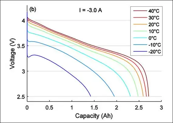
How do temperature and aging shift what the device actually sees?
Temperature and aging change reaction speed and impedance, so they change both steady voltage and pulse behavior.
Cold conditions tend to increase sag and slow recovery. Aging can reduce pulse capability at the same remaining capacity.
A long-life design must validate performance at cold temperature and late life.
A “good” lab result at room temperature can still fail in winter. Field planners should treat Voltage Stability as a life-of-product metric. This is why designers should test the worst case: a cold start when the cell is no longer new.
Cold starts amplify sag and extend recovery
Cold slows ion transport and increases losses during a burst.
In practical terms, internal resistance becomes more important, and the system can see deeper sag at the same peak current.
A lithium thionyl chloride cell can still support long-life work, but the design must treat cold performance as normal, not rare.
If the product has enough local buffering, the buffer can supply the peak current while the cell supplies the average energy.
That approach reduces the chance of a second voltage drop during repeated bursts and keeps the rail more predictable.

Controlled depassivation allows the battery to quickly recover to its normal voltage plateau under load.
A good plan also validates late-life pulse behavior, because many systems fail when margin shrinks over time.
Field Conditions That Should Be in Your Test Plan
| Condition | What typically changes | What to validate |
|---|---|---|
| Cold start | Higher sag during peak events | Minimum rail voltage at the load |
| Late-life pulses | Lower peak capability | Recovery time before next task |
| Storage + first burst | Slower initial recovery | First transmission or actuation |
Plan thresholds from duty-cycle data
A discharge curve under duty-cycle testing tells you what the electronics will see, so it should drive thresholds and alarms.
Firmware should avoid sampling the rail during a burst, because that can bias the reading and trigger false “low battery” events.
Hardware should keep enough dropout headroom so that the regulator stays in control when the rail sags.
It also helps to log minimum rail voltage during qualification tests and compare that log across temperatures and aging states.
That way you can connect lab expectations to field reality and keep the design focused on Voltage Stability instead of guesswork.
Which system steps keep long-life devices stable in the field?
Long-life stability comes from matching chemistry to the duty cycle, buffering peak events, and validating the full power path. Layout, connector choices, and measurement timing can be as important as the cell selection.

When these steps are combined, the system avoids resets and keeps predictable maintenance intervals.
This section is a pillar summary because stability is not a single knob.
In our reviews, Voltage Stability is the first pass/fail gate. The best results appear when the team treats power as part of the product, not as a part number.
Start from the load profile and specify the pass criteria
A lithium primary battery should be chosen after the team defines the real current profile.
That profile includes base drain, burst amplitude, burst width, rest time, and the minimum acceptable rail voltage at the load pin.
You should also define a clear end-of-life rule, because late-life behavior[8] can look different from early-life behavior even at the same average drain.
When the profile is defined, you can test it at cold temperature and with an aged condition model.
Voltage stability improves when the pass criteria are explicit and repeatable. These tests reduce debate, because they turn “should work” into measured limits that match the device’s true operating conditions.
A battery with very high energy density may store more total energy, but if its voltage drops sharply under load or changes significantly during discharge, the system may not be able to use that energy effectively.
System Actions That Improve Long-Life Results
| Action | What it targets | Why it works |
|---|---|---|
| Local buffering | Peak current demand | Keeps the rail above cutoff |
| Short, robust power path | Wiring and connector losses | Cuts avoidable sag |
| Timed voltage sampling | Measurement bias | Prevents false alarms |
Where this battery category fits best
A Lithium Metal Battery is a useful category when you need long storage, long service life, and a predictable energy source without recharge management.
Still, the system must handle pulses and cold starts, and it must validate the full power path to the load.
If the load demands sharp bursts, a buffer and a clean layout often deliver the biggest improvement.
When those steps are present, you can keep stable rails and avoid hidden failure modes that show up only after months in the field.
Conclusion
Voltage Stability keeps industrial power predictable because it prevents resets during bursts and keeps measurements meaningful.
A duty cycle shows voltage drop from internal resistance, so teams should design for the peak, not the average.
Engineers should read the discharge curve under the real pulse schedule and set clear cold and late-life pass limits. With the right lithium primary battery plus local buffering and a clean power path, a Lithium Metal Battery platform can support years of dependable service.
Note:
[1]Discover the significance of the power path in maintaining voltage stability.↪
[2]Discover the effects of brownouts on voltage stability and how to mitigate them.↪
[3]Explore the role of voltage regulators in ensuring stable voltage levels in systems.↪
[4]Discover how voltage margin analysis helps in assessing voltage stability.↪
[5]Find out how real-time monitoring can enhance voltage stability in battery systems.↪
[6]Learn how duty cycles influence voltage stability and battery performance.↪
[7]Discover how local energy buffers can improve voltage stability during peak loads.↪
[8]Understand how late-life behavior can impact voltage stability and performance.↪
Also read further information about lithium metal battery:
- The Ultimate Guide to Lithium Metal Battery for Professionals
- What Makes the Science Behind Lithium Thionyl Chloride Battery So Unique?
- The 3.0V Standard: Unlocking the Power of Lithium Manganese Dioxide Batteries
- How to Choose Between Lithium Metal vs Lithium Ion?
- Beyond 500 Wh/kg: Lithium Metal Battery Energy Density Under Real IoT Load Conditions
- The Science of the Plateau: Why Voltage Stability is the Lifeline of in Power System
- Operating Temperature Range: How temperature affects lithium metal battery performance
- The Real Cost of Cheap Batteries: How High Self Discharge Rate Increase Your TCO
- The Silent Shelf-Life Secret: Why Battery Passivation is Actually a Good Thing
- Mechanical Robustness: Designing Robust Battery That Survive Shock, Vibration, and Long-Term Stress
- Lithium Metal Batteries for Long-Life Industrial Applications: Design and Performance Insights
- Thermal Runaway Prevention: Why Factory-Level Testing is Non-Negotiable for Lithium Battery Safety
- Lithium Metal Battery Long Term Cost Analysis: Initial Price vs Lifetime Value
- Solid state batteries vs lithium metal batteries: Which One Elevates Your Product Performance?

How Does Leakage Current Impact Hybrid Supercapacitors and Li-SOCl₂ Batteries in Low-Power Devices?
Leakage current quietly drains energy from low-power devices long before engineers notice performanc

Battery Performance in Extreme Conditions: Li-SOCl₂ vs LiPo in Harsh Industrial Environments
Cold kills batteries fast, and outdoor monitoring at -40°C pushes most chemistries to their limits.

Hybrid Charge–Discharge Dynamics of Lithium Batteries + Supercapacitor Systems: A Technical Deep Dive
Are you struggling with premature battery failure in industrial meters or IoT devices due to high-pu