


How to Choose the Best Wildfire Detection Sensor Battery
Wildfire monitoring is becoming increasingly sensor-driven.
In 2026, NASA’s FireSense program continued field testing new wildfire-observation instruments, while other projects explored distributed ground sensors that monitor conditions directly in forests and other fire-risk environments. [1] In September 2026, for example, a field demonstration in Meymac, France used solar-powered LoRaWAN sensor nodes to detect smoke and transmit measurements remotely. The nodes normally reported every two hours but switched to continuous reporting once their smoke classification exceeded an alert threshold. [2]
That example does not mean every wildfire sensor uses the same power architecture. Some systems rely on solar-assisted rechargeable batteries, supercapacitors, wired power or other forms of energy harvesting.
But it illustrates an important battery-engineering problem:
A remote sensor may spend most of its life consuming very little energy, then suddenly increase sensing, processing and wireless activity when conditions change.
For a low-power wildfire or forest monitoring node designed around a long-life primary battery, the duty cycle may look like:
Deep sleep → wake → sense → process → transmit → return to sleep
Under abnormal conditions, however, it may become:
Sense → process → transmit → re-sense → retransmit → remain active longer
The battery must therefore be sized for lifetime energy, but validated against the worst-case active or alarm-event waveform.
That distinction is central to selecting a reliable wildfire detection sensor battery.
Featured Snippet: What Battery Is Suitable for a Wildfire Detection Sensor?
A remote wildfire sensor may use a long-life primary lithium battery such as Li-SOCl₂ when average power consumption is very low and field maintenance is difficult. However, the correct battery depends on sensor duty cycle, wireless transmission current, operating temperature, deployment life and minimum system voltage. Applications with stronger short-duration communication pulses may require a spiral Li-SOCl₂ design or an ER + HPC pulse-support architecture.
Table of Contents
- 1. Why Remote Wildfire Sensors Create a Unique Battery Challenge
- 2. What Really Determines Wildfire Sensor Battery Life?
- 3. How to Choose Between Li-SOCl₂, ER-Only and ER + HPC
- 4. What OEMs Should Specify Before Selecting a Wildfire Sensor Battery
- 5. Conclusion
- 6. Frequently Asked Questions
- 7. References
1. Why Remote Wildfire Sensors Create a Unique Battery Challenge
Difficult-to-Service Locations Change the Battery Requirement
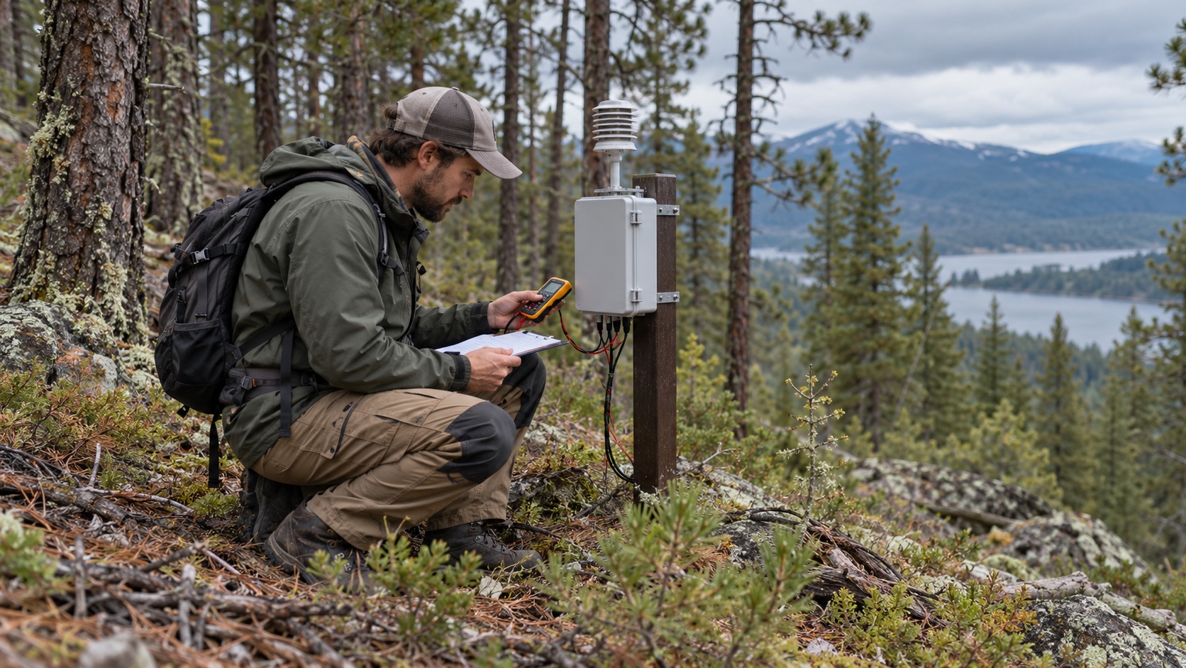
Remote wildfire and environmental monitoring nodes may be installed in forests, mountainous terrain, utility corridors, communication-limited areas or other locations where routine maintenance is inconvenient.
Replacing a battery in these environments is not simply a matter of replacing the cell. Field service may involve technician travel, site access, difficult terrain, maintenance scheduling, equipment coordination, locating distributed sensor nodes and verifying the system after replacement.
For that reason, battery service life becomes a field-maintenance and system-availability parameter, not merely a number on a battery datasheet.
The issue becomes even more important at network scale. A battery strategy that appears acceptable in a ten-node pilot can create a very different maintenance problem when hundreds or thousands of devices are installed across a large geographic area.
What Actually Consumes Power in a Wildfire Sensor Node?
There is no single standard wildfire sensor architecture. Depending on the application, a remote node may contain some combination of:
- temperature and humidity sensing,
- smoke or particulate sensing,
- CO, CO₂ or other gas sensing,
- microcontroller processing,
- local or edge analytics,
- data storage,
- LoRa or LoRaWAN communication,
- NB-IoT or LTE-M,
- proprietary sub-GHz radio,
- GNSS,
- satellite communication,
- status indicators,
- regulators and power-management electronics.
Not every device contains all of these functions.
A 2026 peer-reviewed wildfire-monitoring prototype, for example, used Zigbee to connect near-ground temperature and humidity sensor nodes and LoRa for longer-range communication to a gateway. Its prototype architecture used solar-assisted lithium-ion power rather than a primary battery. [3]
That matters because battery selection must begin with the actual system architecture, not with the application name.
The most useful input for battery engineering is therefore the measured system-level current waveform. Datasheet values for the MCU, radio and sensors are useful during early design, but they do not necessarily reveal startup transients, regulator losses, retransmissions or interactions between subsystems.
Deep Sleep Does Not Describe the Whole Duty Cycle
An ultra-low-power node may spend more than 99% of its time doing very little electrically. That does not mean the entire system behaves like a constant microamp load.
| Operating State | Typical Function |
|---|---|
| Deep sleep | MCU and peripherals remain in the lowest practical power state. |
| Wake-up | Clock, regulator and required peripherals start. |
| Sensor warm-up | Gas, particulate or other sensors stabilize where required. |
| Measurement | Environmental data is acquired. |
| Processing | Filtering, thresholding or local analytics are performed. |
| Radio startup | The wireless subsystem initializes. |
| Transmission | A data packet is sent. |
| Receive / acknowledgement | The device waits for a network response where applicable. |
| Return to sleep | Peripherals shut down and the system returns to standby. |
Engineers should also include loads that are easy to overlook, such as regulator quiescent current, sensor-rail leakage, pull-up networks, protection circuits, memory retention and DC/DC conversion losses. When the main load has been reduced to microamp levels, these background currents can become a meaningful part of the lifetime energy budget.
Normal Reporting and Alarm Reporting Must Be Modeled Separately
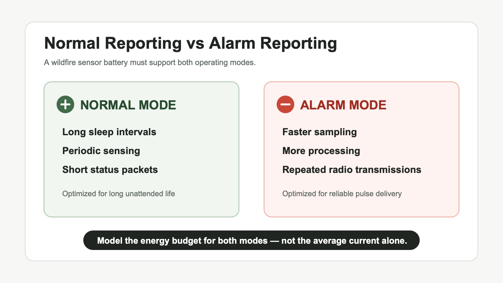
Wildfire monitoring creates a particularly important distinction between normal operation and abnormal-event operation.
During normal monitoring, a node might wake periodically, energize one or more sensors, take a measurement, process the data, transmit a short status packet and return to sleep.
If smoke, particulate, gas, temperature or another monitored variable crosses a system-defined condition, the device may instead sample more frequently, activate additional sensing functions, process more data, transmit more often, request acknowledgements, retransmit failed packets or remain awake longer.
The exact alarm algorithm depends on the OEM and should not be assumed. However, the electrical principle is real. During the September 2026 Meymac field test, the solar-powered LoRaWAN sensors moved from routine reporting every two hours to continuous reporting after their smoke classification crossed the alert threshold. [2]
Average current during routine monitoring may determine much of the lifetime energy consumption, but alarm-mode activity may determine the worst pulse and voltage requirement.
Temperature Is an Electrical Design Variable
A remote forest sensor may experience cold nights, strong daytime solar exposure, seasonal temperature variation and rapid daily temperature changes. Temperature can affect battery impedance, usable capacity, loaded voltage, pulse response, passivation behavior, self-discharge, regulator efficiency, sensor current and radio behavior.
Research comparing spiral and bobbin Li-SOCl₂ cells confirms that cell architecture and temperature both influence impedance behavior. [6]
Testing should therefore consider the expected battery temperature inside the enclosure, not only local weather-station ambient temperature. A sealed outdoor enclosure exposed to sunlight can reach a battery temperature significantly different from ambient conditions.
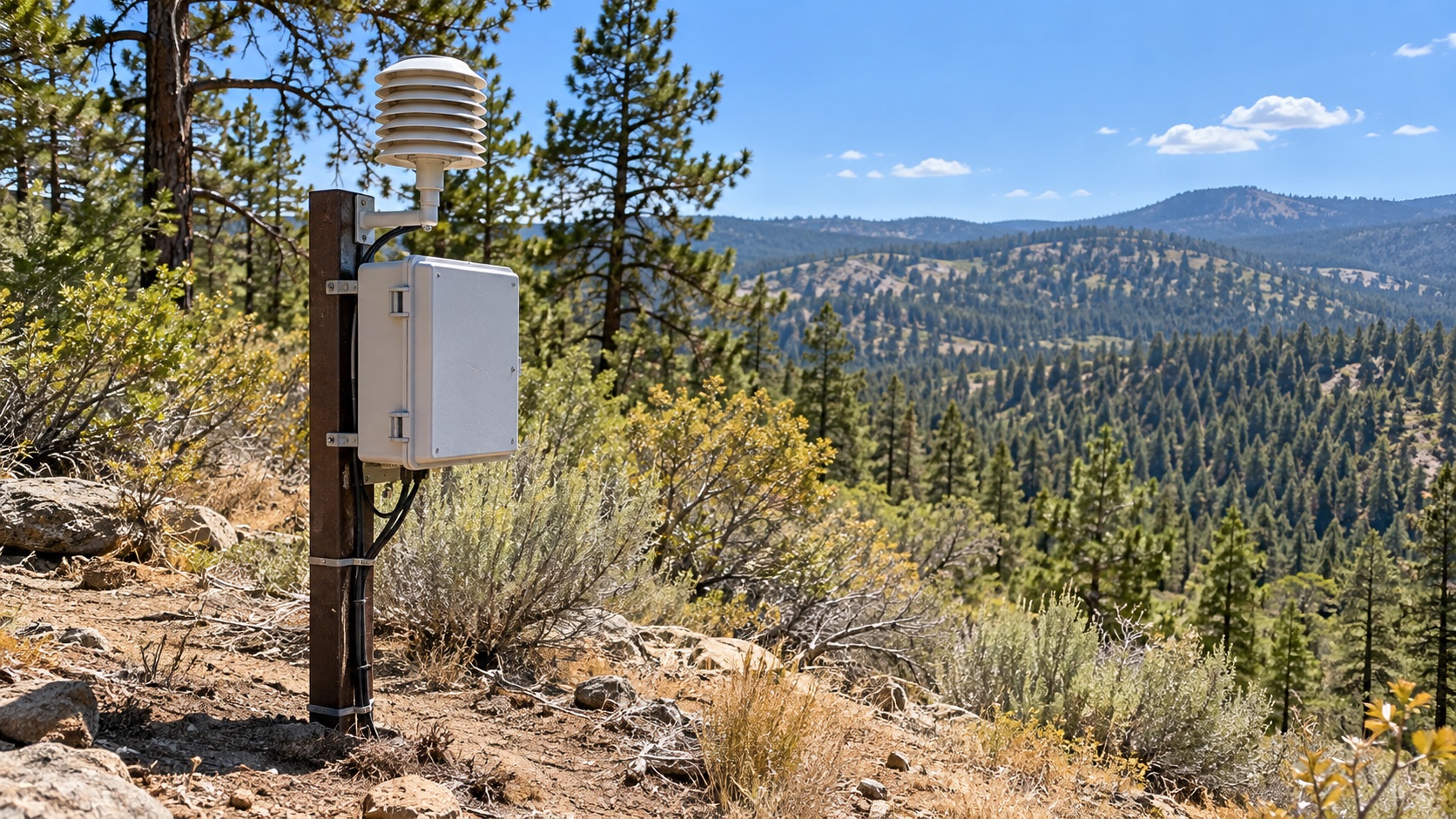
A wildfire monitoring node is intended for early detection or environmental monitoring. A Li-SOCl₂ battery should not be assumed to operate normally after direct flame exposure or at temperatures beyond its specified operating range.
2. What Really Determines Wildfire Sensor Battery Life?
Energy Requirement and Pulse Requirement Are Different Problems
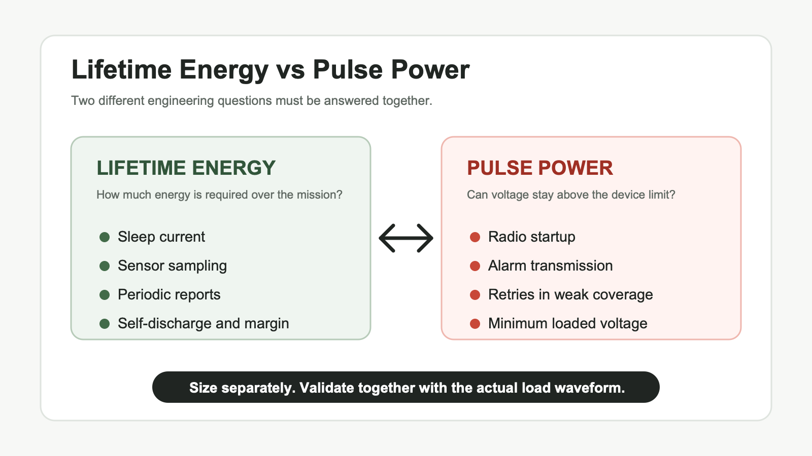
Battery selection should separate two engineering questions.
1. Lifetime energy
How much total energy will the device consume over the required service interval? This is usually evaluated in Ah or Wh.
2. Transient power
Can the battery maintain sufficient voltage while the device draws a substantially higher current for a short period?
These events may occur during radio transmission, cellular network attachment, sensor startup, GNSS acquisition, alarm reporting or repeated retransmissions.
A battery can contain enough nominal energy for the target service life and still fail if a transmission pulse pulls the system below its minimum operating voltage.
Nominal Ah therefore cannot be used as the only battery-selection parameter.
Wireless Communication Can Define the Worst Load
LoRa / LoRaWAN
LoRaWAN is designed for low-power end devices, but transmission energy still depends on reporting interval, transmit power, data rate, airtime, spreading factor, payload size, acknowledgements, retransmissions and network conditions.
The LoRaWAN specification includes Adaptive Data Rate, which allows the network to manage parameters such as data rate and RF output power to improve network capacity and end-device battery efficiency where the deployment supports it. [4]
A low daily message count does not automatically guarantee long battery life if each communication event has excessive airtime or repeated retries.
NB-IoT / LTE-M / Cellular
Cellular IoT creates a different current profile. Network registration, connection establishment and transmission may draw substantially more energy than deep sleep.
A 2026 experimental NB-IoT study found that worsening radio conditions increased connection time, retransmissions and total energy consumption. [7]
This is particularly relevant in forests, valleys and remote utility corridors where RF coverage can vary significantly between deployment sites. Battery calculations should therefore consider not only successful transmissions, but also connection attempts + retries + extended network activity.
Satellite and Other Remote Links
Highly remote systems may use satellite or proprietary sub-GHz communication. These technologies have different current waveforms, but the battery-engineering method remains the same: measure the complete communication event rather than selecting the battery from average current alone.
A Better Way to Estimate Lifetime Energy
A first-order battery estimate is often written as:
Battery life ≈ battery capacity ÷ average current
This is useful for early comparison, but it is insufficient for a multi-year remote sensor. A more realistic model should separate the application’s operating states.
Lifetime energy =
deep-sleep energy
+ sensor warm-up energy
+ measurement energy
+ processing energy
+ memory / peripheral energy
+ communication energy
+ acknowledgement / receive energy
+ retry energy
+ alarm-event energy
+ regulator quiescent consumption
+ conversion losses
+ battery self-discharge
+ design margin
For systems using multiple voltage rails, a Wh-based energy model may be clearer than adding currents directly, because regulator efficiency and voltage conversion can then be represented explicitly.
The second check is equally important:
Will the source remain above the system’s minimum operating voltage during the worst transient load?
That should be evaluated at beginning of life, after storage, at the relevant temperature extremes, in a partially discharged condition and near the end of the required service interval.
Why Self-Discharge Matters
Li-SOCl₂ is attractive for many long-duration primary applications partly because of its high energy density and low self-discharge characteristics. A 2026 review in the Journal of Energy Chemistry identifies high energy density, broad temperature capability and low self-discharge among the chemistry’s principal advantages. [5]
However, low self-discharge does not mean zero self-discharge. In a sensor whose electronics consume relatively little energy, battery self-discharge can become a meaningful part of the total lifetime energy budget.
This is why nominal capacity should not simply be divided by measured device current and treated as guaranteed field life. The longer the intended deployment, the more important storage history and long-term capacity retention become.
Passivation Must Be Considered in Sudden Wake-Up Loads
Li-SOCl₂ batteries naturally form a protective film on the lithium surface during storage. This passivation layer helps suppress parasitic reactions and contributes to the chemistry’s low self-discharge and long storage characteristics.
Passivation is therefore not simply a defect.
However, the same protective layer can temporarily increase the effective source impedance after long storage or extended periods at very low load. When a significant load is suddenly applied, the cell may initially show voltage delay or loaded-voltage depression before recovering. The relationship between the lithium surface film, storage conditions and voltage delay has been documented in Li/SOCl₂ research for decades. [8]
This matters in remote sensors because the operating sequence may be:
long low-current period → wake-up → sensor startup → immediate RF transmission
The correct validation question is not “Does the cell have passivation?” It is:
After the expected storage and operating history, will the loaded voltage remain above the system cutoff during the required event?
For a deeper explanation of the chemistry and application implications, see LONGSING’s battery passivation guide.
3. How to Choose Between Li-SOCl₂, ER-Only and ER + HPC
Why Li-SOCl₂ Can Suit Long-Duration Remote Sensors
Li-SOCl₂ primary batteries can be a strong candidate for remote environmental monitoring when the application combines very low average current, long deployment duration, difficult maintenance access, long idle periods, limited battery volume and a compatible current profile.
But this does not mean Li-SOCl₂ is automatically the best wildfire sensor battery. A sensor with reliable solar input may be better served by a solar-assisted rechargeable system. A continuously active, high-power node may require another battery chemistry or a different power architecture.
The decision should be based on the load profile and operating environment, not on the application label.
Bobbin-Type vs Spiral-Type Li-SOCl₂
Li-SOCl₂ cells can use different internal architectures. Two important examples are bobbin and spiral designs.
Peer-reviewed electrochemical research shows that geometry materially affects impedance behavior: spiral designs use greater electrode surface area and can support stronger current delivery, while bobbin construction can accommodate more active material and favor long-duration energy storage in the same general size class. [6]
| Battery Design | Best Fit | Main Advantage | Main Limitation | When to Consider It |
|---|---|---|---|---|
| Bobbin-type Li-SOCl₂ | Very low average current, long-duration monitoring | High stored energy and strong long-term storage characteristics | Higher impedance can limit sudden high-current response | Long-sleep sensor with modest pulse requirements |
| Spiral-type Li-SOCl₂ | Higher-current or more frequent active loads | Lower impedance and stronger current capability | Typically trades some capacity for power capability | Sensor with higher or more frequent transmit loads |
| ER + HPC | Low average energy demand combined with significant burst loads | Separates long-term energy storage from short-duration pulse delivery | Greater component and integration complexity | Radio or alarm pulses cause unacceptable voltage sag from ER-only |
The important point is not that one architecture is universally better. It is that cell geometry changes the balance between stored energy and current delivery. LONGSING’s bobbin vs spiral battery guide provides a more detailed application comparison.
When ER-Only May Be Sufficient
A standalone ER Li-SOCl₂ cell may be appropriate when:
- average current is low,
- pulse current is within the cell’s validated capability,
- pulse duration is short enough,
- pulse frequency is limited,
- loaded voltage remains above the system minimum,
- temperature does not create unacceptable impedance,
- end-of-life performance still satisfies the load.
For a compact, low-energy node, an ER14505-class cell may be considered if the complete energy and current profile allows it. For applications requiring substantially more stored energy, larger formats such as ER34615 may be evaluated.
These model names identify candidate cell formats, not guaranteed wildfire-sensor solutions. Published product values must be interpreted under their stated test conditions and verified against the actual device waveform.
When ER + HPC Should Be Evaluated
A Hybrid Pulse Capacitor does not replace the long-duration energy source. In an ER + HPC architecture, the ER cell provides long-term stored energy while the HPC supports short-duration high-power events.
This architecture is worth evaluating when:
- the standalone ER cell meets the lifetime-energy requirement but not the pulse-voltage requirement,
- alarm reporting creates repeated communication bursts,
- NB-IoT, LTE-M, GNSS or another subsystem produces significant transient current,
- low temperature or passivation reduces voltage margin,
- the minimum system voltage is relatively high,
- the application must retain pulse capability near end of life.
LONGSING’s IoT Battery Pack / ER + HPC category includes pulse-support configurations for industrial IoT development. One available Website A example is ER26500 + HPC1520.
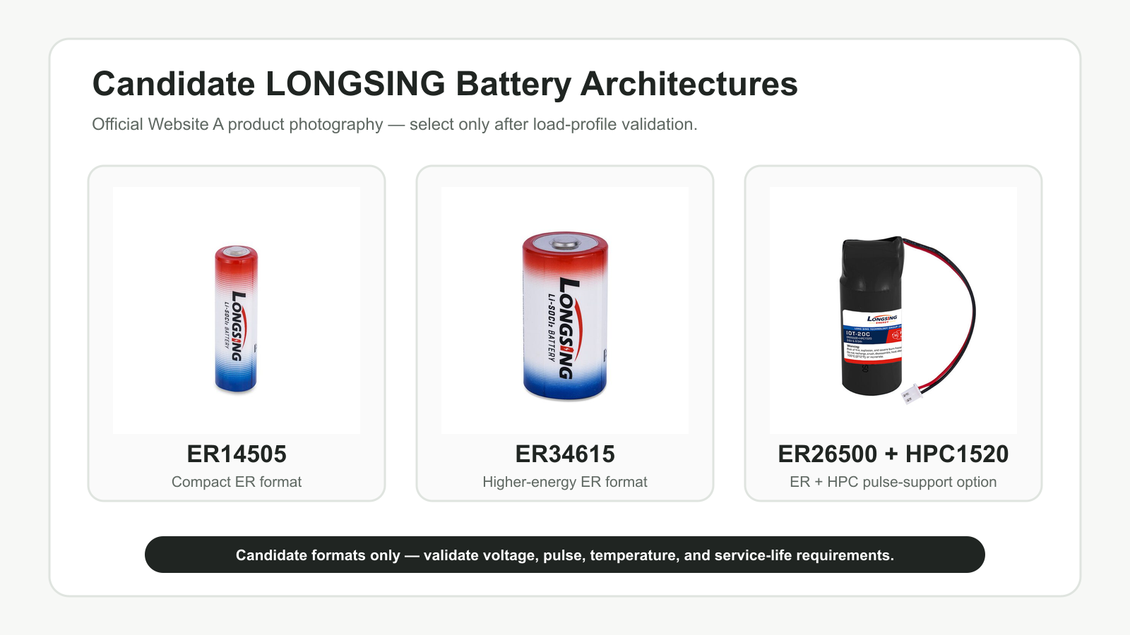
That example should still be treated as a candidate architecture. Pulse duration, repetition, temperature, battery age, minimum system voltage and the real communication waveform must be validated in the target equipment. Product specifications should not be generalized beyond their published test conditions.
A Practical Selection Sequence
Measure the complete device waveform
↓
Calculate the lifetime energy requirement
↓
Select an ER size with appropriate energy margin
↓
Test the worst active and alarm-event pulse
↓
Compare loaded voltage with the system minimum
↓
Repeat under temperature, storage and state-of-life conditions
↓
Keep ER-only if it passes; evaluate spiral ER or ER + HPC if it does not
4. What OEMs Should Specify Before Selecting a Wildfire Sensor Battery
A battery supplier cannot confirm a suitable architecture from the words “wildfire sensor” or “LoRaWAN node” alone. The RFQ should describe the complete electrical, environmental and mechanical requirement.
Electrical and Lifetime Inputs
- nominal operating voltage,
- minimum system voltage,
- deep-sleep current,
- MCU standby current,
- sensor type and operating current,
- sensor warm-up time,
- processing current and duration,
- required deployment interval,
- scheduled reporting interval,
- expected number and duration of alarm events,
- end-of-life energy reserve.
Wireless and Alarm-Mode Inputs
- wireless protocol and device class,
- radio or modem model,
- TX and RX current waveforms,
- transmission duration and payload behavior,
- acknowledgement strategy,
- retry and repetition behavior,
- normal reporting sequence,
- alarm reporting sequence,
- expected RF coverage conditions,
- GNSS or satellite communication events where applicable.
The most useful test record is a synchronized current and battery-terminal-voltage capture of the complete event.
Mechanical and Environmental Inputs
- maximum battery length and diameter,
- available enclosure volume,
- installation orientation,
- wire, tab or connector requirements,
- expected battery temperature range,
- typical daily and seasonal temperature profile,
- humidity and condensation conditions,
- shock and vibration requirements,
- service-access limitations,
- transport and regulatory requirements.
The enclosure must provide the environmental protection required by the system. A battery chemistry should not be assumed to make the complete device waterproof, fireproof or suitable for direct flame exposure.
Validation Cases to Include
- fresh-cell normal reporting,
- fresh-cell alarm reporting,
- long-idle first pulse,
- low-temperature communication,
- high-temperature lifetime exposure where relevant,
- poor-coverage connection and retry sequence,
- repeated alarm transmissions,
- partially discharged condition,
- end-of-life pulse event,
- storage-history and passivation condition.
Wildfire Sensor Battery Specification Checklist
| OEM Input | Why the Battery Supplier Needs It |
|---|---|
| Sleep current | Determines continuous multi-year energy consumption. |
| Sensor warm-up and measurement | Defines active sensing energy, especially for gas or particulate sensors. |
| Scheduled reporting interval | Determines recurring communication energy. |
| Alarm-event profile | Captures higher sampling, processing and reporting demand. |
| TX / RX waveform | Defines transient power and event-energy requirements. |
| Pulse duration and repetition | Influences voltage sag and pulse-support sizing. |
| Minimum system voltage | Defines how much stored battery energy is electrically usable. |
| RF coverage condition | Can change airtime, connection duration and retry count. |
| Temperature profile | Affects self-discharge, impedance, capacity and pulse response. |
| Target service interval | Establishes the required long-term energy reserve. |
| Battery-space envelope | Limits the cell sizes and architectures that can physically fit. |
| Environmental enclosure | Defines sealing, mounting and system-level validation requirements. |
Where LONGSING Fits
LONGSING Website A provides primary-lithium and ER + HPC architectures relevant to long-life wireless sensor development. These should be treated as engineering candidates rather than fixed wildfire-sensor solutions.
For a broader system-level workflow covering current profiles, cutoff voltage, temperature, battery customization and validation, see the Website A guide to choosing a long-life battery for remote monitoring.
Conclusion
A reliable wildfire detection sensor battery cannot be selected from average current, nominal capacity or wireless protocol alone.
The power source must store enough energy for years of sleep, sensing and scheduled communication while maintaining sufficient loaded voltage during wake-up, radio transmission and alarm-mode activity. Temperature, self-discharge, passivation, RF conditions, retry behavior, minimum system voltage and state of life all influence the result.
Li-SOCl₂ can suit low-average-power nodes deployed where maintenance is difficult. Bobbin ER cells may favor long-duration energy, spiral designs may suit stronger active loads, and ER + HPC may help when the ER cell contains enough lifetime energy but cannot support the required pulse with adequate voltage margin.
The correct design sizes lifetime energy and transient power separately—then validates them together in the real device.
Developing a Wildfire Detection or Remote Environmental Monitoring Node?
Prepare the system voltage range, minimum cutoff voltage, complete current waveform, sensing schedule, normal and alarm reporting sequences, wireless conditions, temperature profile, target deployment life, enclosure space and connection requirements.
Those inputs allow a battery supplier to compare ER-only, spiral Li-SOCl₂ and ER + HPC architectures without relying on assumptions or unverified product extrapolation.
Frequently Asked Questions About Wildfire Detection Sensor Batteries
Click to explore more information about wildfire detection sensor batteries
1. What battery is suitable for a wildfire detection sensor?
A long-life primary lithium battery such as Li-SOCl₂ may suit a remote wildfire sensor when average power is very low, maintenance is difficult and the device operates within the battery’s specified conditions. The correct choice depends on lifetime energy, wireless pulse current, temperature, minimum system voltage, available space and the normal and alarm duty cycles.
2. Why can Li-SOCl₂ suit remote forest monitoring?
Li-SOCl₂ combines high stored energy with low self-discharge and long storage characteristics, which can suit unattended low-drain equipment. Its pulse response, passivation behavior, temperature performance and end-of-life loaded voltage must still be validated against the real sensor waveform.
3. How should wildfire sensor battery life be calculated?
Calculate energy separately for deep sleep, sensor warm-up, measurement, processing, wireless communication, receive windows, retries and alarm events. Then include conversion losses, battery self-discharge, temperature effects, aging and design margin. Finally, verify that loaded voltage remains above the system minimum during the worst pulse.
4. Why are normal reporting and alarm reporting modeled separately?
A sensor may report infrequently during normal monitoring but sample, process and transmit much more often after an alert condition. Routine operation can dominate lifetime energy, while the alarm sequence can define the worst current pulse and voltage sag.
5. How does LoRaWAN affect wildfire sensor battery life?
LoRaWAN energy depends on reporting interval, TX power, data rate, spreading factor, time-on-air, payload size, receive activity, acknowledgements and retries. Adaptive Data Rate can improve efficiency in suitable deployments, but battery modeling should use the actual network configuration and measured event waveform.
6. How does NB-IoT affect a remote environmental sensor battery?
NB-IoT energy can increase when radio conditions worsen because connection establishment, repetitions and retransmissions may last longer. Forest, valley or remote-corridor deployments should therefore include representative coverage conditions in battery testing.
7. When should ER + HPC be evaluated?
ER + HPC is worth evaluating when the ER cell meets the long-term energy requirement but cannot maintain sufficient loaded voltage during the worst radio, GNSS, sensor-startup or alarm pulse. The decision should account for pulse duration, repetition, temperature, passivation, battery age and system cutoff voltage.
8. What information should an OEM provide to select the battery?
Provide nominal and minimum system voltage, sleep current, sensor and processor loads, complete TX/RX waveform, pulse duration, reporting interval, normal and alarm sequences, retry assumptions, RF conditions, battery temperature profile, target service interval, available dimensions and connector requirements.
References
[1] ↩ NASA FireSense — NASA Heads to the “City of Trees” to Test New Tools for Observing Wildfires.
[2] ↩ SEBELO — Wildfire Detection Sensors Tested Live in Meymac, France.
[3] ↩ Frontiers in Communications and Networks — A Hybrid Zigbee–LoRa Sensor Network with Integrated Machine Learning for Ignition-Stage Wildfire Risk Monitoring.
[4] ↩ LoRa Alliance — LoRaWAN Specification v1.0.3.
[5] ↩ Journal of Energy Chemistry — Li-SOCl₂ Batteries: Current Status, Practical Challenges, and Future Perspectives.
[6] ↩ Journal of The Electrochemical Society — Observing the Effect of Architecture on Spiral and Bobbin Li/SOCl₂ Batteries with Temperature-Dependent EIS.
[7] ↩ IEEE — Experimental Analysis of Performance and Consumption of NB-IoT Device Under Different Radio Conditions.
[8] ↩ Electrochimica Acta — S.E.M. Studies of the Li-Film Growth and the Voltage-Delay Phenomenon Associated with the Lithium-Thionyl Chloride System.

Primary Lithium vs. NiMH Batteries Engineering Trade-Offs for Long-Term Power Applications
When selecting the optimal energy source for critical electronic systems, the comparison of Lithium
Bobbin Type vs Spiral Type Lithium Primary Batteries: Which Design Is Better for Long-Life Applications
Bobbin Type vs Spiral Type lithium primary batteries represent two fundamentally different internal
Key Advantages: Design Considerations for Li-SOCl₂ Military Battery
Li-SOCl₂ military battery technology serves as the tactical energy backbone for modern defense sys