


How to Choose a Long-Life Battery for Remote Monitoring in Smart Grid Systems
Remote grid sensors may operate for years in locations where a truck roll is costly or disruptive. A poorly matched smart grid monitoring battery can cause lost data, resets or premature replacement. Selecting a long-life battery for remote monitoring starts with the complete electrical and environmental duty, not capacity alone.
Choosing a long-life battery for remote monitoring requires analysis of chemistry, usable capacity, continuous and pulse current, temperature, device cutoff voltage, self-discharge and the required unattended service life. Engineers should verify that the battery sustains both cumulative energy demand and short communication pulses under end-of-life and worst-temperature conditions.
The following framework shows how to select a long-life battery for remote monitoring by connecting load profile, chemistry, capacity, pulse validation and pack customization.
Table of Contents
- What Power Challenges Do Remote Smart Grid Monitoring Systems Face?
- Why Are Li-SOCl₂ Batteries Suitable for Long-Term Monitoring?
- How Should Engineers Calculate Battery Capacity and Pulse Demand?
- When Does a Monitoring Device Need a Custom Battery Pack?
What Power Challenges Do Remote Smart Grid Monitoring Systems Face?
A smart grid monitoring battery must support low standby consumption, periodic sensing, data logging and high-current communications across temperature extremes. The correct long-life battery for remote monitoring must also remain above the device cutoff voltage throughout the maintenance interval, including during pulses and near the end of usable capacity.
Translate field duty into electrical requirements
Remote grid sensors rarely draw constant current. A terminal may sleep for most of the day, wake to energize sensors, process data, write to memory and then transmit by cellular, radio or satellite link. Average current determines much of the energy budget, while the peak amplitude, duration and frequency determine whether the voltage remains stable.
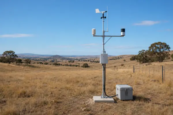
Temperature changes both available capacity and internal resistance. Cold conditions commonly reduce pulse capability and increase voltage sag; heat can accelerate self-discharge and component aging. The enclosure, cable resistance, regulator efficiency and contact resistance also consume voltage margin. A long-life battery for remote monitoring should therefore be evaluated at the battery terminals and at the equipment input, not only on a room-temperature datasheet.
| Parameter | Engineering Relevance | Evaluation Question |
|---|---|---|
| Average current | Sets cumulative ampere-hour demand | What is the time-weighted current across every operating state? |
| Pulse current | Can create transient voltage sag | What are the amplitude, duration and repetition rate? |
| Temperature range | Changes usable capacity and impedance | What temperatures occur inside the enclosure? |
| Cutoff voltage | Defines when the device stops operating | What minimum voltage must be maintained during a pulse? |
Maintenance planning for a long-life battery for remote monitoring must distinguish storage life from operating life. A battery stored under specified conditions is not experiencing the same load, temperature cycling and voltage constraints as one powering unattended monitoring equipment. Calculated life is a design estimate; validated field life requires representative equipment testing and field evidence.
Why Are Li-SOCl₂ Batteries Suitable for Long-Term Monitoring?
A Li-SOCl2 battery pack can be suitable where low self-discharge, high nominal energy and broad temperature tolerance are more important than rechargeability. However, selecting a long-life battery for remote monitoring still requires verification of pulse response, passivation behavior, voltage limits and usable capacity under the actual load.
Benefits and limitations of primary Li-SOCl₂ chemistry
Lithium-thionyl chloride is a primary lithium chemistry: it is non-rechargeable and has no cycle-life specification. Its characteristics can fit industrial IoT battery applications with long sleep periods and infrequent transmissions. Yet low average current does not automatically ensure reliable radio pulses. Cell construction, storage history, temperature and passivation can influence internal resistance and initial voltage response.

The following ER34615-3×6 configuration illustrates how a candidate pack can be screened, but it is not a universal recommendation. This approximately 3S6P Li-SOCl2 battery pack is rated at 10.8 V and 114 Ah when discharged at 12 mA to a 6.0 V endpoint at room temperature, equivalent to approximately 1,231 Wh nominal energy. Nominal capacity is not the same as usable capacity in a real device.
| Parameter | Reference Value | Engineering Interpretation |
|---|---|---|
| Configuration and mass | Approximately 3S6P; 1,800 g | Must fit the enclosure, mounting and weight limits |
| Nominal rating | 10.8 V; 114 Ah; approximately 1,231 Wh | Starting point only; apply load and environmental derating |
| Discharge limits | 900 mA continuous; 1,800 mA pulse | Both limits and transient voltage must satisfy the device |
| Temperature | −55°C to +85°C | Pack capability still requires application-level validation |
| Loss and storage | Average annual capacity loss no more than 2% under specified conditions; 10-year specified storage life | Neither value alone proves 10 years of field operation |
Reference acceptance criteria for this long-life battery for remote monitoring include open-circuit voltage of at least 10.8 V and loaded voltage of at least 9.9 V under 33 Ω for no more than 10 seconds. Specified discharge checks include at least 900 hours at room temperature under 100 Ω, 135 hours at room temperature under 16.5 Ω, 860 hours at 55°C under 100 Ω and 340 hours at −40°C under 100 Ω, each to a 6.0 V endpoint. These are pack-reference tests, not claims about service life in a particular device.
For a long-life battery for remote monitoring, safety and application testing should be defined separately. IEC 60086-4:2025 specifies safety tests and requirements for primary lithium batteries under intended use and reasonably foreseeable misuse; it does not replace equipment-specific runtime and pulse validation.
How Should Engineers Calculate Battery Capacity and Pulse Demand?
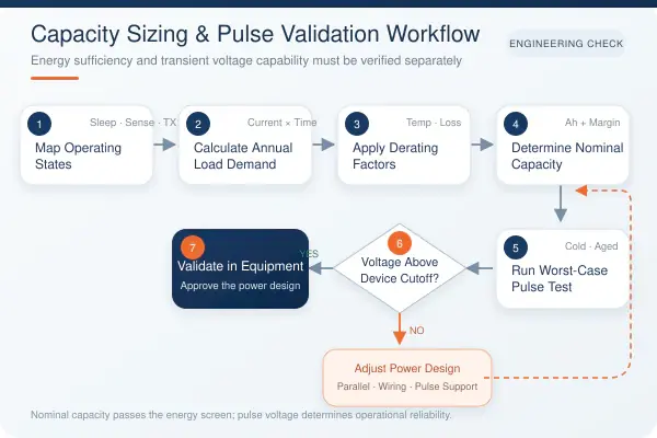
Battery sizing begins with charge consumed in every operating state, then adds allowances for temperature, self-discharge, conversion losses, cutoff voltage and design margin. A smart grid monitoring battery must also pass worst-case pulse tests: adequate nominal ampere-hours cannot prevent failure if transient voltage falls below the equipment threshold.
Calculate energy first, then verify voltage under pulse
For each state, calculate charge as current multiplied by time, and sum all states over the target interval. A practical screening equation is: required nominal capacity = total load demand ÷ usable-capacity factor ÷ retention factor × design margin. Every factor should be justified by cell data and tests rather than selected as a generic percentage.
U.S. transmission DLR example and illustrative failure analysis
The U.S. Department of Energy documented a New York Power Authority dynamic line-rating demonstration using battery-powered EPRI sensors, onsite weather instruments and other monitoring methods; rating calculations were performed at ten-minute intervals. The project designed and tested field instrumentation, power and communications, but the public report does not publish the sensors' battery current profile. See the DOE Dynamic Line Rating Systems report.
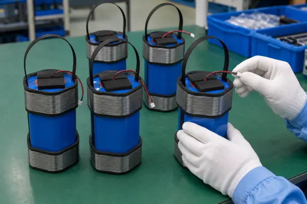
The numbers below are therefore an illustrative engineering calculation, not NYPA electrical data and not a LONGSINGX customer deployment. To screen a long-life battery for remote monitoring, assume a U.S. electric-transmission sensor samples locally every ten minutes, averages 0.25 mA including sensing and logging, and transmits an aggregated record once per hour at 1.2 A for one second. It needs ten years of unattended operation.
Annual standby demand is 0.00025 A × 8,760 h = 2.19 Ah. Radio demand is 1.2 A × 1 s × 8,760 ÷ 3,600 = 2.92 Ah, for 5.11 Ah annually and 51.1 Ah over ten years. If analysis supports a 70% usable-capacity factor, 82% retention factor and 10% margin, the screen becomes 51.1 ÷ (0.70 × 0.82) × 1.10 = approximately 98 Ah. A 114 Ah reference pack clears the energy screen, but that does not complete the design.
| Case Element | Documented or Illustrative Input | Engineering Decision |
|---|---|---|
| Country, industry, equipment | United States; electric transmission; dynamic line-rating sensor | Support remote utility asset monitoring and periodic data delivery |
| Average and pulse load | Illustrative: 0.25 mA average; 1.2 A for 1 second hourly | Size energy and test transient voltage separately |
| Capacity screen | Illustrative: approximately 98 Ah required | Select only after factors are supported by data |
| Validation | Actual device, aged samples, cold and hot temperatures, end-of-life simulation | Record battery-terminal and device-input voltage during transmission |
| Failure and correction | Pulse sag below cutoff despite remaining capacity | Add parallel capability or pulse support, reduce resistance, or revise radio duty |
At −40°C or after long storage, a 1.2 A pulse may pull voltage below the device cutoff voltage even when substantial nominal capacity remains. Symptoms include communication failure, reset, shortened service life or premature shutdown. Corrective actions may include more parallel cells, a suitable pulse-assist component, lower-resistance wiring and connectors, a revised transmission profile, or a different cell design. The final long-life battery for remote monitoring must pass pulse validation after representative storage, temperature exposure and discharge.
When Does a Monitoring Device Need a Custom Battery Pack?
A custom pack is justified when voltage, runtime, pulse demand, connector, enclosure, temperature or regulatory requirements cannot be met by a standard battery. The smart grid monitoring battery specification should be frozen only after the battery load profile, mechanical interface and validation plan have been agreed.
From device data to a validated pack specification
A standard pack may be adequate when its voltage window, current limits, size and termination already match the equipment. Customization becomes relevant for unusual series-parallel arrangements, low-temperature pulses, installation geometry, keyed connectors, lead length, mounting, insulation or application-specific protection. A custom primary lithium battery should not be specified merely to increase nameplate capacity; the system-level problem must be defined first.
| Project Step | Typical Activity | Required Output |
|---|---|---|
| 1 | Collect device voltage and load profile | Operating states and input limits |
| 2 | Analyze average and pulse current | Energy budget and transient requirement |
| 3 | Select cell chemistry | Documented chemistry rationale |
| 4 | Define series-parallel configuration | Voltage, capacity and current architecture |
| 5 | Select connector and lead wire | Polarity, resistance and interface specification |
| 6 | Define insulation, spacing and fixation | Mechanical drawing and material requirements |
| 7 | Inspect open-circuit and loaded voltage | Acceptance limits and inspection record |
| 8 | Perform required discharge, pulse and temperature tests | Results against the agreed validation plan |
| 9 | Validate samples in customer equipment | Device-level approval or corrective actions |
| 10 | Complete production and quality inspection | Released build and inspection criteria |
Not every test or protection feature applies to every project. Rechargeable systems may require a BMS, while a primary Li-SOCl2 battery pack may instead use application-appropriate fusing, isolation or pulse-support provisions. The applicable safety and transport requirements must be established for the destination and end equipment.
LONGSINGX is based in Hong Kong, collaborates with NAMI on R&D and is OEM manufacturer that operates a smart manufacturing facility in mainland China. Project support can include pack configuration, connectors, lead wires, mechanical structures, samples and agreed testing. For any long-life battery for remote monitoring, the customer equipment remains the final validation platform.
Conclusion
Selecting a long-life battery for remote monitoring requires more than comparing nominal ampere-hours. Engineers should match chemistry and usable capacity to the real load profile, pulse demand, temperature, device cutoff voltage and target maintenance interval. A smart grid monitoring battery should be sized analytically, tested under worst-case conditions and validated in the equipment before field deployment.
Keep Reading further on Lithium Primary Batteries
- Lithium Primary Batteries: Types, Performance, and Selection Guide
- Choosing Li-SoCl₂ High Capacity Battery for IoT, Metering, and Monitoring Systems
- Key Advantages: Design Considerations for Li-SOCl₂ Military Battery
- Bobbin Type vs Spiral Type Battery Long-Life Applications
- 2026 Procurement Outlook: Navigating Lead Times and Raw Material Trends in Lithium Coin Cell Battery
- CR123A, CR17450, and CR14505 The Ultimate CR Li-MnO2 Cylindrical Battery Comparison
- Survival in -40°C: Li-SOCl2 vs. Li-Po battery for Outdoor Monitoring
- Lithium D Batteries for Industrial Applications: Specifications, Lifespan, and OEM Solutions
- Primary Lithium vs. NiMH Batteries Engineering Trade-Offs for Long-Term Power Applications
- Battery Selection Guide: Primary vs Secondary Lithium Batteries for Industrial Projects?
- Solid state batteries vs lithium metal batteries: Which One Elevates Your Product Performance?
- Looking for LS14500 equivalent? Reliable Power Supply on Lithium ER14505 Battery for OEMs
- Top OEM Lithium Primary Battery Manufacturers for Industrial Projects in 2026

Mechanical Robustness: Designing Robust Battery That Survive Shock, Vibration, and Long-Term Stress
Many industrial devices fail early because their power source breaks under stress. This creates down

Thermal Runaway Prevention: Why Factory-Level Testing is Non-Negotiable for Lithium Battery Safety?
Lithium battery safety begins long before a cell is integrated into a device; it is a critical bench
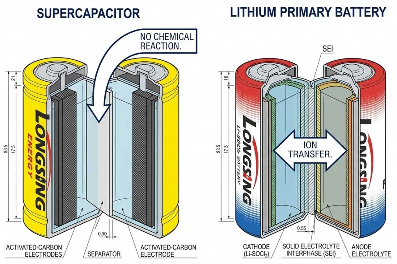
Are supercapacitors safer than batteries?
Supercapacitors are inherently safer than batteries due to electrostatic storage, yet batteries rema