

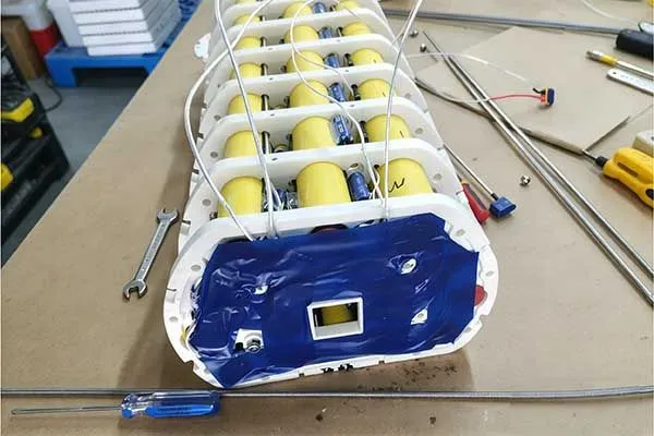
Subsea Primary Battery Solutions for AUVs, ROVs, and Oceanographic Sensors
Key Takeaways
- A subsea primary battery suits AUVs, ROVs, and oceanographic sensors that need high energy density and no recharging.
- Lithium thionyl chloride cells give 3.6V per cell and very low self-discharge, supporting multi-year ocean deployments(under sleep current in the μA range).
- The load profile, not nameplate capacity, determines what the battery must power underwater.
- Mission duration equals usable capacity, after derating and reserve, divided by average current.
- Validation must cover hydrostatic pressure, cold temperature, pulse loads, and leak integrity before deployment.
- Most failures trace to pressure ingress, voltage delay, or insufficient current margin, and each has a defined corrective action.
Underwater robots fail when power fails. Alkaline packs fade in cold, high-pressure seawater, and rechargeable cells need surfacing. A pressure-housed subsea primary battery built on lithium thionyl chloride delivers stable 24V energy for years, reducing vehicle-recovery cycles.
A subsea primary battery for AUVs, ROVs, and oceanographic sensors should combine high-energy lithium thionyl chloride cells, a pressure-tolerant housing, and a load-matched pack design.
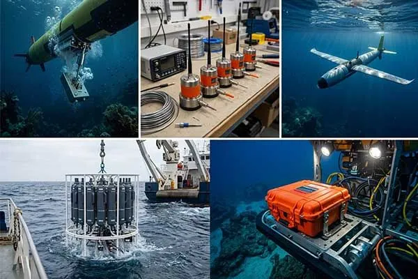
Typical solutions group 3.6V Li-SOCl2 cells into 24V packs inside 1 ATM vessels or pressure-balanced, oil-filled enclosures. They deliver predictable energy for weeks to years without recharging, provided capacity is sized to the mission profile and validated under pressure and cold.
Before you choose capacity or housing, you need to know what the vehicle demands. The sections below cover loads, sizing, validation, and failure control, in that order.
Table of Contents
- What Does a Subsea Battery Need to Power?
- How to Calculate Subsea Battery Capacity and Mission Duration?
- How to Validate a Subsea Battery Before Deployment?
- Subsea Battery Failure Analysis: What Are the Symptoms, Root Causes, and Corrective Actions?
1. What Does a Subsea Battery Need to Power?
A subsea battery must power propulsion, navigation, sonar, payload sensors, communications, and a safe-recovery reserve, often at 24V, in near-freezing, high-pressure water. Continuous loads of 5 to 20A, short pulses, and long standby periods set the design. The battery must deliver this without maintenance, leaks, or voltage collapse throughout deployment.
What Are the Subsea Power Challenges in Marine Robotics?
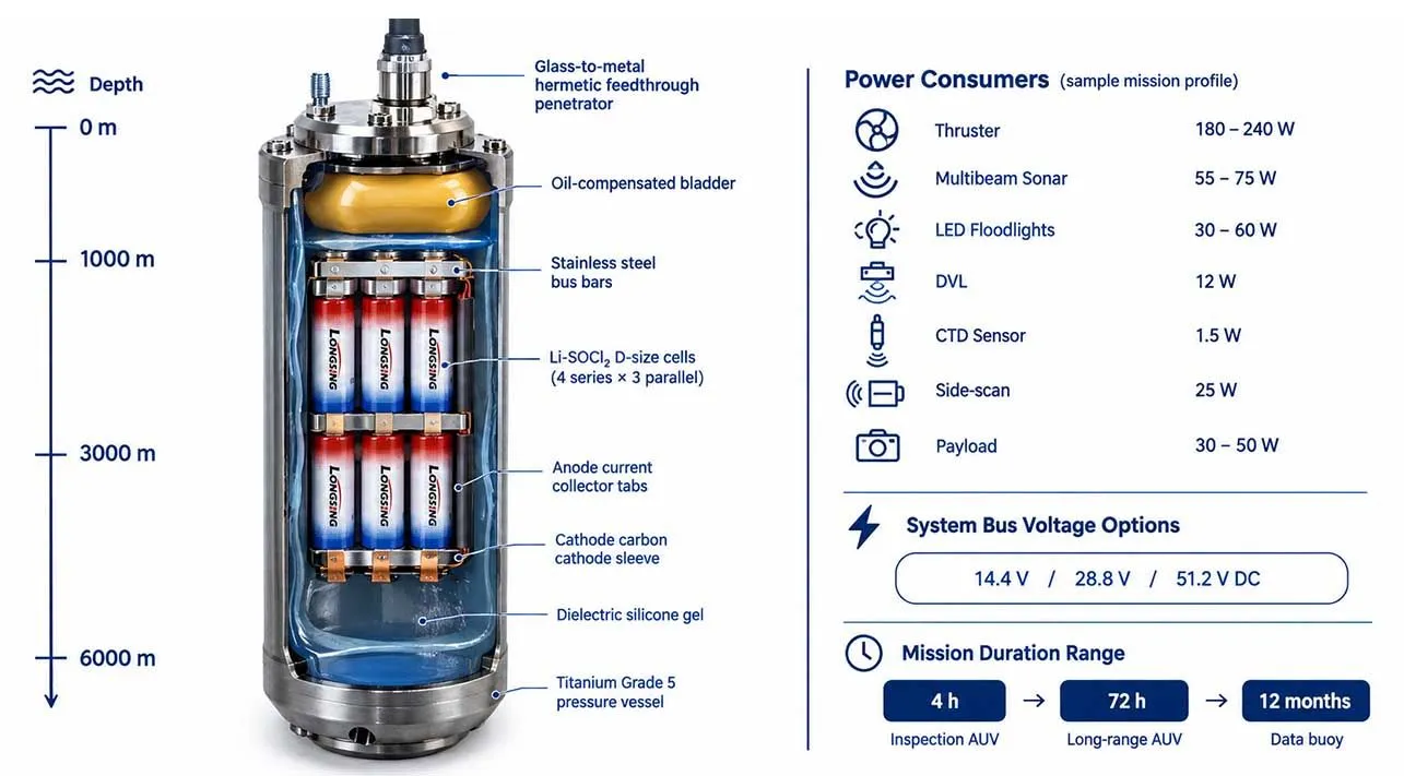
Every underwater robot carries its own energy. Once it passes a few hundred meters, there is no cable, no charger, and no second chance. A common belief is that a battery cannot be exposed to water. The real hazard is not water touching a sealed cell. It is seawater bridging live conductors, corroding terminals, or crushing an unsupported case.
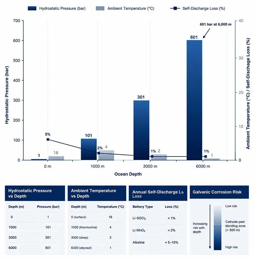
In a pressure-balanced design[1], cells sit in dielectric oil, fully surrounded by liquid, because equal pressure inside and out removes the crushing load.
Hydrostatic pressure rises about 1 bar per 10 meters, so a 3,000 m dive means roughly 300 bar. Cold bottom water, typically 2 to 4 °C, raises internal resistance in most chemistries. Pulse loads from thrusters and sonar add voltage stress. As the author of many pack designs, I treat these three factors as one coupled problem, not separate checklist items.
| Challenge | Effect on Battery | Design Response |
|---|---|---|
| Hydrostatic pressure | Case deformation, seal leakage | 1 ATM vessel or oil-filled compensation |
| Near-freezing water | Higher resistance, lower capacity | Derating, low-temperature electrolyte cells |
| Thruster and sonar pulses | Voltage dips, early cutoff | Hybrid supercapacitor, current margin |
| No recharge opportunity | Mission ends at depletion | Primary chemistry, reserve capacity |
What Are the Battery Requirements in AUVs and ROVs?
An AUV battery pack carries the entire mission, so energy density and reliability dominate. An ROV battery often supports backup and tooling loads while the tether supplies the main power. A UUV battery sits between the two, depending on autonomy level.
The reference pack below uses a marine grade Li-SOCl2 battery cell in a 24V lithium thionyl chloride battery format.
| Parameter | Specification |
|---|---|
| Nominal voltage | 24V class (7S, 25.2V nominal) |
| Cell type | D-size Li-SOCl2, 19 Ah, 3.6V |
| Configuration | 7S80P |
| Rated capacity | 1520 Ah |
| Continuous discharge current | 20 A |
| Peak pulse current | 40 A (hybrid supercapacitor assisted, ≤ 2 s) |
| Nominal energy | ≈ 38 kWh |
| Operating temperature | −55 ~ +85 ℃ |
| Self-discharge | < 1% per year at 20 °C |
| Depth capability | Up to 3,000 m oil-filled; deeper with 1 ATM vessel by its wall thickness design |
| Protection | String fuses, blocking diodes, thermal monitoring |
Two housing approaches exist. A 1 ATM pressure vessel keeps internal pressure at one atmosphere, so cells never feel the ocean, but thick walls add weight. A pressure-balanced oil-filled structure uses a compensator bladder to equalize pressure, giving a lighter pressure-housed battery.
In subsea systems, Li-SOCl₂ batteries are commonly used for:
- AUV emergency release mechanisms — reliable backup activation after long standby.
- Acoustic beacons and emergency pingers — long-duration underwater signaling.
- Underwater gliders — lightweight power source for autonomous missions.
- CTD and oceanographic sensors — stable energy for long-term monitoring.
- Subsea vehicle black boxes — backup power for critical data preservation.
Chemically, Li-SOCl2 cells form a lithium chloride passivation layer that enables low self-discharge but causes voltage delay after storage. Pairing the pack with a hybrid supercapacitor covers pulse peaks while the cells supply steady current.
2. How to Calculate Subsea Battery Capacity and Mission Duration?
Calculate mission duration[2] by converting the load profile to average current, multiplying usable capacity by derating and reserve factors, then dividing by average current.
Mission duration = usable capacity ÷ average current
For example, a 380 W AUV at 24V draws about 15.8A. A 1520 Ah pack derated by 0.85 for rate and temperature and 0.90 for reserve yields about 73 hours.
How Do You Convert a Load Profile Into Mission Hours?
Start from subsystem power, not from a catalog capacity. Weight each load by its duty cycle, sum to average watts, then divide by pack voltage. This applies equally to an underwater robot, a primary lithium battery for underwater robotics, or a long-duration ocean glider power solution, though a glider's averages are far lower.
| Subsystem | Power (W) | Duty Cycle | Average (W) |
|---|---|---|---|
| Propulsion | 250 | 100% | 250 |
| Navigation and DVL | 30 | 100% | 30 |
| Sonar | 80 | 50% | 40 |
| Payload sensors | 15 | 100% | 15 |
| Computer and communications | 45 | 100% | 45 |
| Total | 380 |
Average current is 380 W ÷ 24V = 15.8 A. Usable capacity is 1520 Ah × 0.85 × 0.90 ≈ 1,163 Ah. Mission duration is 1,163 ÷ 15.8 ≈ 73 hours.
The rate-and-temperature derating factor reflects lower delivered capacity in cold water at higher current. The reserve factor protects the safe-recovery sequence. Skipping either one is the most common sizing error I see.
Case Study: A German AUV Integrator — From First Inquiry to Serial Supply
A subsea systems integrator in northern Germany approached Long Sing Technology in March 2025, while building an inspection AUV for offshore cable surveys. Their rechargeable pack delivered 18 hours, and each charging turnaround blocked the survey vessel for two days. They wanted a single-deployment mission above 60 hours.
| Mission Phase | Duration (h) | Avg Current (A) | Ah Consumed | Key Subsystems Active |
|---|---|---|---|---|
| Launch, descent & transit | 5 | 17 | 85 | Thrusters, INS, DVL, depth control |
| Cable route survey | 35 | 20 | 700 | Side-scan sonar, sub-bottom profiler, data recorder |
| Close inspection & CP measurement | 12 | 18 | 216 | LED lights, HD camera, CP probe, altimeter |
| Return transit & ascent | 5 | 17 | 85 | Thrusters, INS, DVL, ballast pump |
| Surface standby & recovery | 16 | 7 | 112 | Iridium beacon, GPS, strobe |
| Total | 73 | 16.4 avg | 1,198 | — |
Our chief engineer Wilson Lu used the load profile above. The 73-hour result gave about 22% margin over the 60-hour target. We built two 24V packs in 7S80P format, each with 1520 Ah rated capacity and 20 A continuous current, in a pressure-balanced oil-filled enclosure.
Testing: Over four weeks, the customer and our lab ran 300 bar hydrostatic cycling[3], discharge at 4 °C and 15.8 A, and 40 A thruster-pulse trials. The pack delivered about 1,196 Ah to a 21.0V cutoff, against the 1,163 Ah prediction. This is one of the successful project leading from samples that brings into real-world order scenarios.
3. How to Validate a Subsea Battery Before Deployment?
Validate a subsea battery with a sequence of electrical characterization at target temperature, pulse testing, hydrostatic pressure cycling beyond rated depth, leak and insulation checks, and abuse testing. Transport and safety evidence typically references UN 38.3 and IEC 60086-4:2025[4], while subsea qualification practice often draws on API 17F principles[5] for control equipment.
Which Deep-Sea Battery Testing Steps Matter Most?
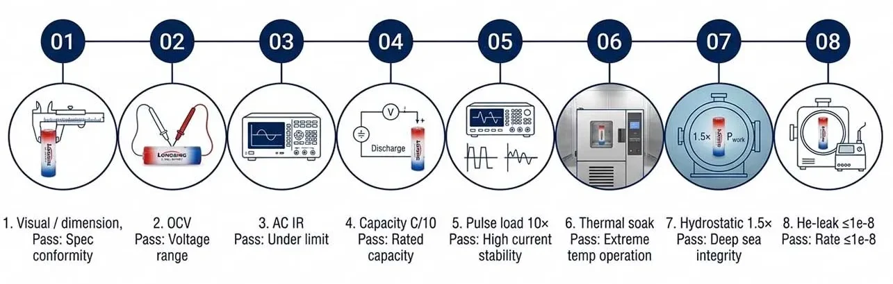
Deep-sea battery testing should reproduce the mission, not just the datasheet. Pressure cycling above rated depth exposes seal and compensator weaknesses that static tests miss. Pulse testing at cold temperature exposes voltage delay. Insulation checks before and after pressure cycling catch microscopic ingress.
| Test | Condition | Pass Criterion |
|---|---|---|
| Capacity at temperature | 4 °C, mission current | ≥ predicted usable capacity |
| Pulse response | 40 A, 2 s, cold start | Voltage above electronics cutoff |
| Hydrostatic pressure cycle | 1.25× rated depth, multiple cycles | No leakage, no deformation |
| Insulation resistance | Before and after pressure | No measurable degradation |
| Abuse and safety | Short, vent, thermal checks | No fire or rupture |
Validation also has limits. A passed tank test does not prove a seabed deployment, because thermal gradients and long soak times are hard to replicate. I recommend adding a shallow field trial before committing a full mission.
Why Does Chemistry Selection Change the Validation Plan?
Lithium thionyl chloride battery for subsea applications offers high energy density and low self-discharge, but its passivation behavior and non-rechargeability change what you test.
Lithium-ion cells need charge-management and thermal runaway validation, which adds mass and complexity to a submarine batteries design.
| Chemistry | Approx. Energy Density | Rechargeable | Cold Performance | Typical Subsea Role |
|---|---|---|---|---|
| Li-SOCl2 | 500 – 700 Wh/kg | No | Good to −45 °C | Long-duration missions, standby |
| Li-MnO2 | 250–300 Wh/kg | No | Moderate | Mid-power instruments |
| Lithium-ion | 150–250 Wh/kg | Yes | Poor below 0 °C | Frequent-cycle vehicles |
| Alkaline | 100–150 Wh/kg | No | Poor | Short, low-cost trials |
A fair counterpoint is that rechargeable packs win when a vehicle surfaces daily and cycles many times. Primary cells win when deployment is long and recovery is expensive.
4. Subsea Battery Failure Analysis: What Are the Symptoms, Root Causes, and Corrective Actions?
Common subsea battery failures include early voltage cutoff, reduced delivered capacity, ground faults, and housing leaks. Root causes are usually voltage delay after storage, undersized current margin in cold water, seal degradation, or oil contamination.
Corrective actions include pre-depolarization, hybrid pulse support, derating, redesigned seals, and strict pressure-cycle validation.
What Do Common Failure Modes Look Like?
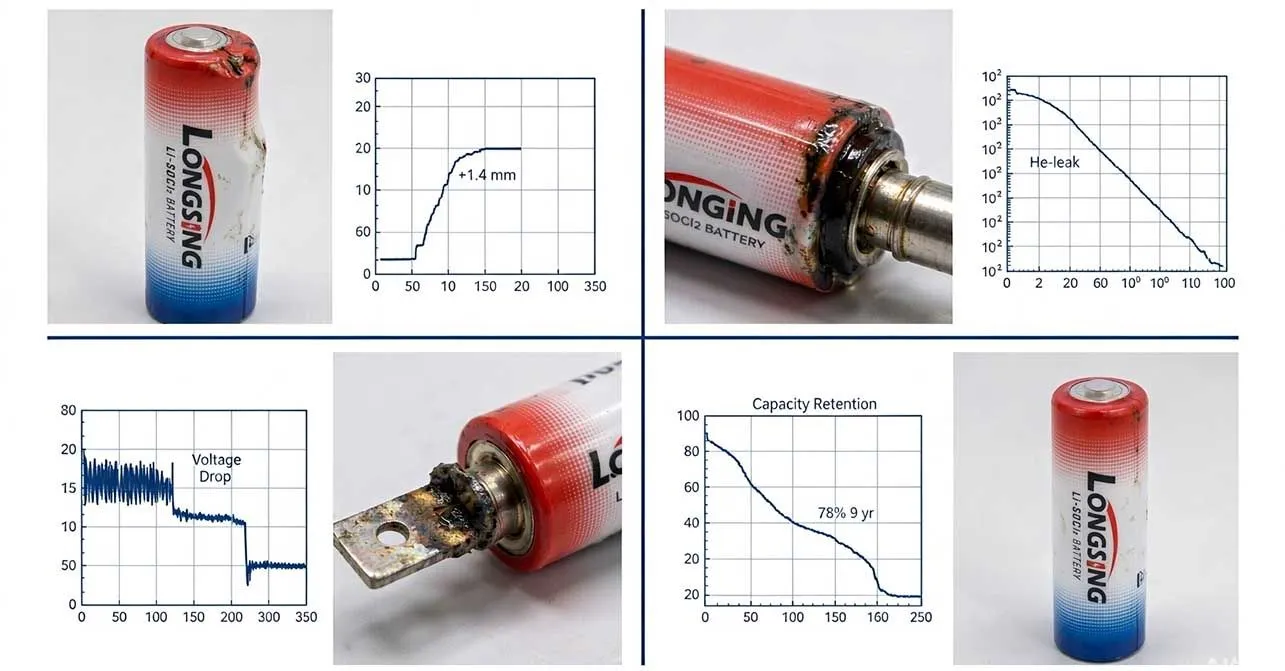
Failures rarely appear as sudden events. They appear as trends in logged voltage, current, and insulation data. Reading these early separates a fixable design issue from a lost vehicle.
| Symptom | Root Cause | Corrective Action |
|---|---|---|
| Voltage dip at power-on | Voltage delay from passivation | Pre-depolarization load, supercapacitor support |
| Mission ends early | Cold derating ignored | Re-size with temperature factor |
| Ground fault alarm | Oil or seawater ingress | Seal redesign, insulation test |
| Housing deformation | Compensator failure | Bladder inspection, pressure retest |
| Capacity shortfall after storage | Excess self-discharge | Storage-condition control, lot testing |
What Does a Long-Duration Ocean Observation Case Show?
A coastal observatory operator needed an oceanographic battery for a benthic lander carrying a subsea data logger. The prior pack was four alkaline D cells. Before: it stopped at about 9 months because cold water cut delivered capacity and self-discharge consumed reserve.
The logger sleeps at 25 µA and wakes for 20 seconds at 30 mA every 30 minutes. Average current is about 0.36 mA. Over a 24-month deployment (17,520 h), the load consumes about 6.3 Ah. Seabed temperature was 3 °C, and self-discharge was around 0.7% per year.
After: the operator switched to a single D-size Li-SOCl2 cell (19 Ah), providing a benthic lander battery pack with roughly 3× margin. On recovery after 24 months, the cell measured 3.58V open-circuit and 3.41V under a 30 mA pulse. The same approach suits an underwater nav system backup battery and battery for underwater sensors, where long standby matters more than peak power.
Frequent Asked Questions about subsea primary battery:
(Click to Unfold)
Q: What is an AUV?
A: An autonomous underwater vehicle (AUV) is an uncrewed underwater robot that follows a preprogrammed mission without continuous operator control. It uses onboard navigation, sensors, and power systems to collect oceanographic data, map the seabed, inspect underwater environments, or conduct scientific surveys. For long-duration missions, primary lithium batteries such as lithium thionyl chloride (Li-SOCl2) may power low-average-load instruments, while hybrid pulse capacitors can support demanding current pulses when the system is designed for this combination.
Q: How are submarines powered?
A: Submarine power systems depend on the platform. Nuclear submarines use onboard nuclear reactors, while conventional submarines typically use diesel generators when surfaced or operating with air access and batteries for submerged propulsion. Uncrewed underwater vehicles use mission-specific battery systems sized for propulsion, sensors, communications, and operating duration. Long Sing Technology’s Li-SOCl2 cells and hybrid pulse capacitor battery packs are potential power solutions for suitable low-power subsea instruments and autonomous platforms, subject to load, safety, and pressure-protection requirements.
Q: What is the difference between an AUV and an ROV?
A: An AUV (autonomous underwater vehicle) navigates underwater without continuous operator control, typically following a programmed mission. An ROV (remotely operated vehicle) is controlled by an operator, commonly through a tether that can provide communications and, in some systems, power. Both platforms may carry cameras, sonar, and scientific sensors. Battery selection depends on mission duration, peak current, available space, and power architecture. Li-SOCl2 cells paired with hybrid pulse capacitors may suit certain long-life instruments with intermittent high-current demands.
Q: Can a submarine be powered by solar energy or batteries?
A: Batteries can power conventional submarines underwater, while solar energy is generally impractical as a direct propulsion source for submerged submarines because sunlight penetrates only shallow water. Solar panels can, however, support surface vessels or recharge systems between missions when suitable. Small AUVs and oceanographic instruments commonly rely on batteries for underwater operation. Primary Li-SOCl2 batteries can provide long service life for low-average-power sensing, while hybrid pulse capacitors can help meet intermittent peak-current demands when correctly engineered.
Q: How does the increasing use of autonomous underwater vehicles change the strategic role of manned submarines?
A: Autonomous underwater vehicles extend underwater surveillance, seabed mapping, reconnaissance, and mine-countermeasure capabilities without placing crews directly at the point of operation. They can complement manned submarines by collecting distributed data or performing selected high-risk tasks, while crewed platforms retain roles requiring human judgment, endurance, command functions, or larger payloads. Reliable onboard power is essential for long-duration missions. Battery design must account for energy demand, pulse loads, temperature, pressure protection, and mission-specific safety requirements.
Q: What are autonomous underwater vehicles (AUVs), and what are they used for?
A: Autonomous underwater vehicles are uncrewed robotic platforms that perform underwater missions using onboard navigation and control systems. Applications include oceanographic research, bathymetric mapping, environmental monitoring, offshore infrastructure inspection, and underwater surveys. Their battery systems must balance energy capacity, peak power, operating temperature, packaging, and mission duration. Long Sing Technology supplies Li-SOCl2 primary cells and hybrid pulse capacitor battery-pack solutions for suitable subsea sensing and monitoring applications, with final designs determined by the equipment’s electrical and environmental requirements.
Conclusion
A subsea primary battery succeeds when its design follows the mission, not the catalog. Define the load profile, convert it to average current, apply cold and reserve derating, and choose a pressure-tolerant battery architecture, either a 1 ATM vessel or a pressure-balanced oil-filled enclosure. Validate with hydrostatic cycling, cold pulse tests, and insulation checks. Finally, monitor trends to catch failures early. With these steps, Li-SOCl2 packs power AUVs, ROVs, and sensors reliably.
Note:
[3]Learn why hydrostatic cycling tests are essential for validating deep-sea battery reliability.↪
[4]Check IEC 60086-4:2025 requirements for lithium primary battery safety testing and compliance.↪
[5]Explore API 17F principles used for subsea equipment qualification and reliability practices.↪
How Lithium Ion Capacitors Bridge the Gap Between Batteries and EDLCs
Struggling with power backups that either drain too fast or lack burst energy? Standard batteries de

Supercapacitors vs Ultracapacitors: Electrical Characteristics You Should Know
Engineers designing long-life, high-reliability backup power systems often struggle to choose betwee

How to Maximize Electronic Shelf Label Battery Life
An electronic shelf label may consume very little power on its own. The challenge appears when a ret