


How to Avoid Primary Lithium Battery Series and Parallel Mistakes
A remote meter can run normally on the bench and still reset in service when its radio transmits after a long idle period. Another device may have enough battery capacity but not enough input voltage, while a sealed sensor simply needs more deployment energy than one cell can store. In each case, adding cells looks like the obvious answer.
The connection itself is easy to draw. The engineering consequence is not. Series and parallel arrangements change what happens when one cell ages faster, a radio pulse pulls the voltage down, a parallel branch warms up, or the equipment keeps operating after one cell is nearly depleted. They also change protection, transport documentation, and the evidence needed for release.
For that reason, primary batteries in series and parallel should be treated as alternative system architectures—not as a quick way to multiply a catalogue voltage or capacity figure.
A multi-cell primary battery pack must be engineered as a complete power system, not treated as a group of independent cells.
Quick Answer
Yes—primary lithium cells can be used in series, parallel, or series-parallel packs designed for a specific device. Series adds voltage. Parallel keeps approximately the same voltage while increasing theoretical Ah capacity and current capability. The arithmetic is simple; the risk analysis is not. A weak series cell can be driven into reversal, and unequal parallel branches can exchange current. Cell model, production history, loaded voltage, temperature, cutoff behavior, interconnect resistance, branch protection, and the real current waveform all matter. Matching cells is essential, but it does not replace pack-level protection or testing in the finished equipment.
- Why OEM Devices Use More Than One Primary Lithium Cell
- What Changes When Primary Batteries Are Connected in Series?
- What Changes When Primary Batteries Are Connected in Parallel?
- Why Primary Battery Pack Design Differs from Rechargeable Pack Design
- Cell Consistency and Production Control
- Protection and Pack-Level Safety Considerations
- How to Size a Series or Parallel Primary Battery Pack
- Validation Tests Before Production
- What OEMs Should Specify to the Battery Supplier
- Choosing the Right Architecture
- Where LONGSING Fits
- Conclusion
- Frequently Asked Questions
- References
1. Why OEM Devices Use More Than One Primary Lithium Cell
Start with the limitation in the device. If the input rail is too low, a series string may be logical. If the voltage window is already suitable but the life target is not, compare a larger cell with a parallel design. If the problem appears only during startup or radio transmission, adding Ah may do little to prevent the voltage dip.
Mechanical design can also drive the choice. Several smaller cells may fit around a PCB where one larger cell will not. Safety-critical equipment may use isolated power paths so that one open branch does not remove an essential function. In both cases, packaging and electrical architecture have to be developed together.
Before increasing cell count, compare the multi-cell option with a larger single cell, a power-oriented cell construction, or a converter. For low-average-current devices with short high-current events, a pulse-power design using a Li-SOCl2 cell and a compatible hybrid pulse capacitor (ER + HPC) may be a better fit. That choice still needs application-specific confirmation; an energy-source datasheet alone does not establish pulse performance.

| Design Requirement | Possible Architecture | Main Question to Validate |
|---|---|---|
| Higher equipment voltage | Matched cells in series; or one cell plus a suitable converter | Does the minimum loaded pack voltage remain above the system cutoff through end of life? |
| More deployment energy at the same voltage | Larger single cell; matched parallel cells; or a different form factor | Can branch currents and cross-current be controlled under all allowed conditions? |
| Short, high-current events | Power-oriented cell; ER + HPC; or evaluated parallel architecture | What is the lowest voltage during the worst pulse after storage, at temperature, and near end of life? |
| Restricted enclosure geometry | Multiple smaller cells or a custom-shaped pack | Can spacing, insulation, interconnects, and fault containment fit without creating hot spots? |
| Functional redundancy | Isolated branches or independent power paths | Does one failed, open, or shorted branch leave the required function available without backfeed? |
2. What Changes When Primary Batteries Are Connected in Series?
In a series string, the same current flows through every cell and the voltages add. The common mistake is to add the Ah ratings as well. Do not: for matched cells under ideal conditions, string capacity in Ah remains approximately the capacity of one cell. Stored energy increases because pack voltage is higher.
Nominal pack voltage = number of series cells × nominal cell voltage
Pack energy in Wh ≈ nominal pack voltage × rated Ah
Those equations describe nominal ratings, not energy available to the device. Operation stops when loaded pack voltage crosses the equipment cutoff, even if chemical capacity remains. Temperature, passivation, resistance growth, pulse duration, wiring loss, and the cutoff setting determine when that happens.
Illustrative series calculation
Hypothetical illustration—not a LONGSING product specification: four identical 3.0 V, 2.0 Ah cells produce a nominal 12.0 V, approximately 2.0 Ah string and a 24 Wh nominal energy figure. The string is not 8.0 Ah. Nor should 24 Wh be entered unchanged into a lifetime claim: usable energy has to be checked at the actual load, temperature, and cutoff.
The weakest cell limits the string
A series pack is limited by the first cell that can no longer support the load. That may be the cell with slightly less capacity, higher impedance, a different storage history, or the coldest position in the enclosure. If the equipment continues drawing current, the remaining cells can force the depleted cell through zero volts and into reversal. This is a fault condition, not a charging method.
The cutoff must protect the weakest credible cell, not an average. Pack voltage can mask one depressed cell while others support the total. Li-SOCl2 manufacturer guidance identifies forced discharge in series strings and discusses cell bypass protection as one possible measure.[1] Selection depends on the cell, string voltage, fault analysis, and acceptable loss.
3. What Changes When Primary Batteries Are Connected in Parallel?
Parallel connection is attractive because the headline result is straightforward: nominal voltage stays close to one cell, while theoretical Ah capacity and available current can increase. In real hardware, however, every branch is both a source and a possible current sink.
Ideal parallel capacity = number of parallel cells × individual-cell capacity
The formula assumes equal cells and equal current sharing. A larger Ah label does not prove that each branch will deliver its assigned share, particularly after storage or at temperature extremes. Cell impedance, contact resistance, interconnect layout, cutoff voltage, isolation loss, and aging all shift the result.
Current sharing and cross-current
Parallel current rarely divides evenly. The branch with lower total resistance often carries more of a pulse and therefore heats and depletes differently. The split changes again as cells age, contacts change, or one part of the pack becomes warmer. Equivalent-circuit research shows how capacity and resistance mismatch drive branch imbalance, although the actual magnitude remains application-specific.[2]
A voltage difference between branches can also drive current from the higher-voltage branch into the lower-voltage one, even when the device is nearly idle. For a primary cell, that incoming current is an unintended charging condition. Isolation, branch fusing, or current limiting may be needed, but each measure adds its own voltage drop, leakage, heat, tolerance, and failure mode. The protection cannot be selected independently of the minimum operating voltage.
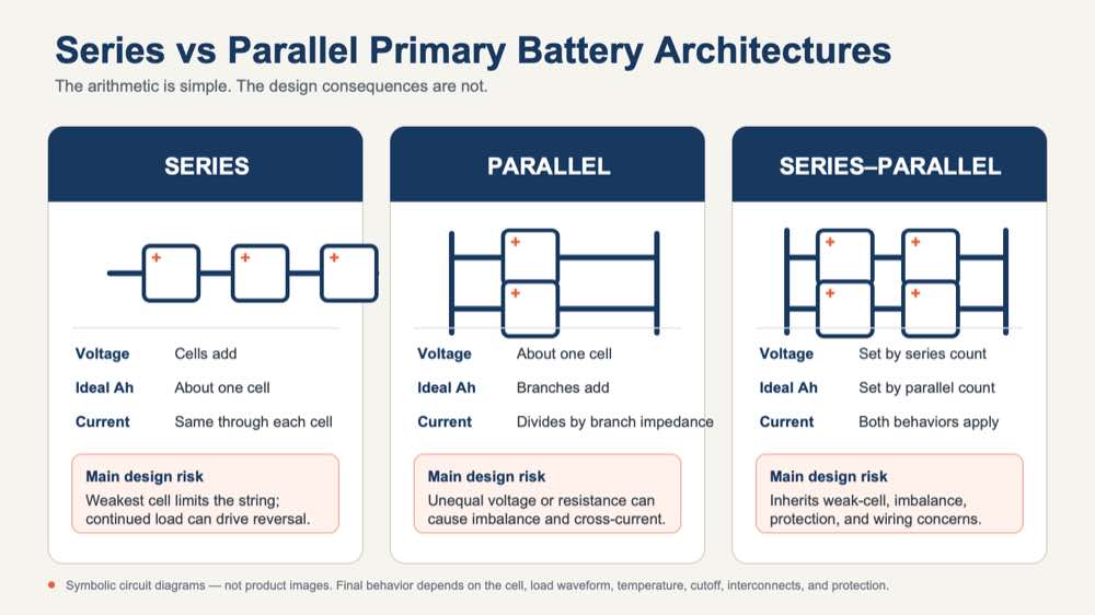
| Parameter | Series Connection | Parallel Connection | Series-Parallel Pack |
|---|---|---|---|
| Nominal voltage | Cell voltages add | Approximately one-cell voltage | Set by cells per series string |
| Ideal Ah capacity | Approximately one matched cell | Branch capacities add | Approximately one string capacity multiplied by parallel strings |
| Primary limitation | Weakest cell and lowest loaded cell voltage | Unequal current sharing and cross-current | Weakest cell plus branch-to-branch imbalance |
| Typical protection focus | Forced-discharge prevention, cutoff, insulation for higher voltage | Branch isolation, fault-current limitation, branch fusing | Coordinated cell, string, branch, and pack protection |
| Validation focus | Cell voltage spread and reversal margin | Branch current over temperature and life | String imbalance, open branch, weak cell, and common-point faults |
4. Why Primary Battery Pack Design Differs from Rechargeable Pack Design
A rechargeable pack can use its charging system to manage cell voltage repeatedly. A primary pack has no equivalent opportunity to restore or rebalance cells in service. Its protection strategy therefore centres on controlled discharge and on preventing unintended charging, forced discharge, and excessive fault current. Panasonic’s primary-lithium guidance treats reverse-current blocking and current limitation as equipment-design responsibilities.[3]
End of life is reached when the equipment can no longer complete its required function under the specified conditions—not simply when a calendar interval expires or a spreadsheet says the Ah budget has been consumed.
This is also why “BMS” is often too vague for a primary pack. State the function instead: reverse-current blocking, current limiting, thermal cutoff, branch isolation, voltage monitoring, or communication. That wording makes design reviews and supplier quotations much clearer.
Li-SOCl2 and Li-MnO2 are not interchangeable
Lithium thionyl chloride batteries are widely considered for long-duration, low-average-current duty. Their passivation behaviour, however, can delay loaded-voltage response after storage; the effect varies with cell design and history.[4] For an intermittent device, the first pulse after a long idle period may be more revealing than a continuous room-temperature discharge.
Lithium manganese dioxide batteries have different voltage, impedance, discharge, and pulse behavior. Official application data show that loaded pulse voltage and device cutoff affect delivered capacity.[5] Neither chemistry should inherit the other’s lifetime model or acceptance limits; form factor and construction also matter.
5. Cell Consistency and Production Control
Cell matching starts before any electrical measurement. Use the same approved chemistry, model, capacity class, and production history; use the same lot where practical. New and used cells—or cells from different suppliers, constructions, ages, or storage histories—do not become compatible simply because their labels show the same voltage.
“Same model number” is only the starting point. Open-circuit voltage can identify a gross outlier, but it says little about pulse response after storage. A useful production screen reproduces a meaningful part of the duty cycle at a controlled temperature and rest condition. The resistance of tabs, welds, wires, contacts, and protective parts belongs in the same assessment.

| Production Check | What It Reveals | Why It Matters |
|---|---|---|
| Identity and traceability | Chemistry, model, lot, date, and approved source | Prevents unintended mixing and supports containment if a deviation appears |
| Open-circuit voltage | Gross voltage outliers after a defined rest and temperature condition | Reduces risk of connecting obviously dissimilar parallel branches |
| Loaded voltage | Voltage response at an application-relevant current and duration | Can identify a cell that would reach device cutoff early |
| Resistance or impedance | Variation in current-delivery behavior under a defined method | Supports current-sharing and pulse-drop analysis; method and temperature must be controlled |
| Storage history and age | Exposure that may affect self-discharge, passivation, seals, or impedance | Cells with different histories can diverge even when they began in one specification class |
| Terminal and weld inspection | Polarity, geometry, weld consistency, insulation clearance, and workmanship | Interconnect resistance and defects can create local heating or unequal branches |
| Pack functional test | Output voltage, polarity, continuity, protection function, and connector mapping | Verifies the assembly rather than assuming that good cells create a good pack |
Matching reduces initial variation; it does not protect the pack from a latent defect, damaged interconnect, cold spot, or unexpected load. Acceptance limits should come from pack testing and remain linked to lot-level traceability.
6. Protection and Pack-Level Safety Considerations
Protection begins with the fault being controlled. A short at the pack connector is different from a weak cell in a series string or a voltage difference between parallel branches. Depending on the design, the response may involve a fuse, PTC, current limiter, diode, cutoff circuit, insulation barrier, keyed connector, or a combination of these.
There is no universal primary-battery protection circuit. A component that blocks reverse current may also reduce the voltage available to the device. A fuse that clears one fault may not respond to a lower, sustained abnormal current. Leakage, tolerance, temperature rating, heat dissipation, and failure mode therefore belong in the minimum-voltage and lifetime calculations—not only in the schematic review.
Commercial primary packs demonstrate that series, parallel, and series-parallel constructions can use electrical or thermal fuses, PTCs, and diodes.[6] They show what is possible, not what should be copied. The appropriate network depends on the selected cell and the device’s credible faults.
Standards have different jobs
Primary lithium battery safety has to be considered at cell, pack, and finished-product levels. IEC 60086-4:2025 addresses primary-lithium safety under intended use and reasonably foreseeable misuse.[7] UL 1642 has a different scope, and UL notes that final acceptability still depends on the battery’s use in a compliant end product.[8]
UN Manual of Tests and Criteria subsection 38.3 concerns transport testing.[9] Passing it does not certify the finished device for its intended market. Likewise, a compliant cell does not automatically qualify a new pack or shipping configuration. Record the exact cell, pack, equipment, destination, and product standard in the compliance plan.
7. How to Size a Series or Parallel Primary Battery Pack
Do not begin sizing with the average current shown in a product brief. Build the load profile from the device states: sleep, sensing, processing, transmission, actuator movement, alarms, startup, retries, diagnostics, and fault recovery. For each state, record current, duration, frequency, operating voltage, and temperature.
Lifetime charge ≈ Σ(current × duration × number of events)
This charge total is a useful first estimate, not a service-life prediction. Add self-discharge over the expected temperature history, converter and protection losses, quiescent current, aging, production variation, and a documented reserve. Where the voltage changes materially, calculate energy by operating state as well; an Ah-only model can hide converter losses and count capacity below the device’s usable voltage.
Separate lifetime energy from transient power
Energy and pulse capability are separate questions. A pack may contain enough Wh and still reset the electronics during transmission. Conversely, a strong pulse from fresh room-temperature cells says little about multi-year life. Test pulse amplitude, duration, repetition, recovery, and retry behaviour with fresh and partially depleted packs at the temperature limits. LONGSING’s battery temperature overview provides context, while the selected cell data and application plan set the limits.
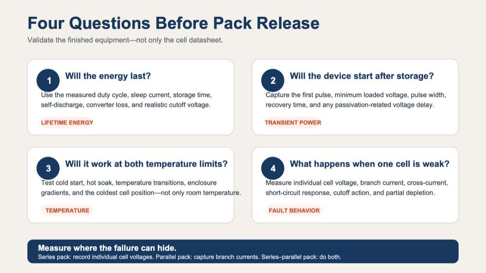
The sizing review should answer four separate questions: will the energy last, will the device start after storage, will it operate at both temperature limits, and will it still complete its worst event near end of life? Where Li-SOCl2 is used, include the first pulse after representative battery passivation exposure.
8. Validation Tests Before Production
Write the pass/fail criteria before testing. “The voltage looked stable” is not an acceptance criterion. Define the minimum pack and cell voltages, maximum temperature rise, permitted branch-current spread, successful startup or transmission, brownout recovery, logging behaviour, and safe shutdown. Then apply those limits across battery state, temperature, load, storage history, and credible faults.
- Fresh-cell steady-load operation across the intended voltage window.
- Maximum pulse load, including pulse trains, retries, and the longest credible event.
- Cold start and hot operation or storage where relevant to the application.
- Partially discharged and end-of-life loaded-voltage behavior.
- The first pulse after a representative long idle or storage interval.
- Branch imbalance, open-branch, high-resistance connection, and weak-cell cases.
- Short-circuit and single-fault review at cell, branch, connector, and pack output.
- Mechanical shock, vibration, enclosure compression, and connector-resistance checks.
- Environmental sealing, condensation, contamination, and corrosion exposure as applicable.
- Transportation configuration, terminal protection, packaging, and documentation review.
Measure at the level where the failure can hide. In a series string, record individual cell voltage as well as pack voltage. In a parallel pack, capture branch current during connection, startup, steady load, pulse load, temperature transition, and partial depletion. A series-parallel design needs both sets of measurements.
Accelerated testing needs a defensible link to field use. Heat, frequent pulses, or continuous loading can change passivation, self-heating, and recovery, so an accelerated result is not exact lifetime proof by itself.
9. What OEMs Should Specify to the Battery Supplier
The most useful RFQ attachment is a measured waveform, not a sentence asking for “a 10-year battery.” Give the supplier enough information to compare a larger single cell, series, parallel, series-parallel, converter, and pulse-support options on the same basis.
| OEM Input | Why the Battery Supplier Needs It |
|---|---|
| Complete voltage window | State the absolute maximum, normal range, and minimum loaded voltage. These values set the cell count and determine how much rated capacity is actually usable. |
| Measured load waveform | Include sleep, active, continuous, peak, startup, pulse duration, repetition, and retry sequences. The waveform exposes power demands hidden by an average-current figure. |
| Duty cycle and service-life target | List event frequency, overlapping loads, expected field life, maintenance interval, and replacement strategy so energy and reserve assumptions can be reviewed. |
| Operating and storage temperatures | Give realistic cell temperatures, not only ambient limits. Storage history affects aging, passivation, first-use response, seals, and available pulse voltage. |
| Mechanical envelope | Provide drawings, keep-out zones, mass limit, cell orientation, retention method, and service access. These details can rule out an otherwise attractive topology. |
| Connector, wire, and interface details | Specify polarity, pinout, wire length and gauge, mating connector, current rating, keying, and permitted voltage drop. |
| Environment and mechanical loads | Define sealing, condensation, contamination, shock, vibration, corrosion, and enclosure compression that can affect insulation and interconnect resistance. |
| Markets, standards, and shipping form | Identify target countries, equipment standards, labeling needs, and whether the battery ships alone, with equipment, or installed in equipment. |
| Forecast volume and quality requirements | Annual quantity, ramp schedule, traceability, inspection, change control, and validation sampling affect assembly and supply planning. |
Flag simultaneous loads. A radio pulse and valve movement may both pass when tested separately but create the real worst case when they overlap. A short oscilloscope capture with voltage, current, and timing is usually more useful than another page of estimated averages.
Have a Voltage Window and Load Profile?
Send the real waveform, temperature range, and service-life target. LONGSING can compare series, parallel, series-parallel, and ER + HPC options.
10. Choosing the Right Architecture for Primary Batteries in Series and Parallel
Choose the topology after the voltage window, waveform, temperature range, and mechanical envelope are known. One larger cell is often simpler because it removes cell-to-cell imbalance, but it may not fit or may not supply the required voltage. Primary lithium batteries in series solve the voltage problem while making the weakest cell decisive. Li-SOCl2 batteries in parallel can add energy or current capability, but they introduce current-sharing and cross-current questions. Series-parallel packs inherit both sets of concerns.
If the energy source is suitable but pulse voltage is not, ER + HPC may deserve comparison with direct paralleling. A different chemistry may suit the waveform or temperature range better. A converter can widen the usable voltage window of one cell, but its efficiency, standby current, startup behaviour, and faults become part of the battery calculation.
A practical decision sequence
- Measure the device voltage window and complete load waveform.
- Calculate energy by operating state, including conversion and standby losses.
- Set the temperature, storage, and end-of-life conditions.
- Compare the simplest single-cell option with series, parallel, and pulse-support candidates.
- Review credible faults and choose protection with its losses included.
- Build samples and test them in the finished equipment.
- Turn the validated limits into production acceptance criteria.
Keep the original test conditions beside every capacity or pulse figure used in the decision. Data measured at one load, temperature, and cutoff cannot be transferred unchanged to another waveform. Where evidence is missing, mark the assumption and close it with a test.
11. Where LONGSING Fits
LONGSING works with primary lithium cells, Li-SOCl2, Li-MnO2, ER + HPC configurations, and customized pack assembly where they fit the application. The custom primary battery packs page outlines this development scope.[10] It should not be read as a blanket recommendation for a particular topology.
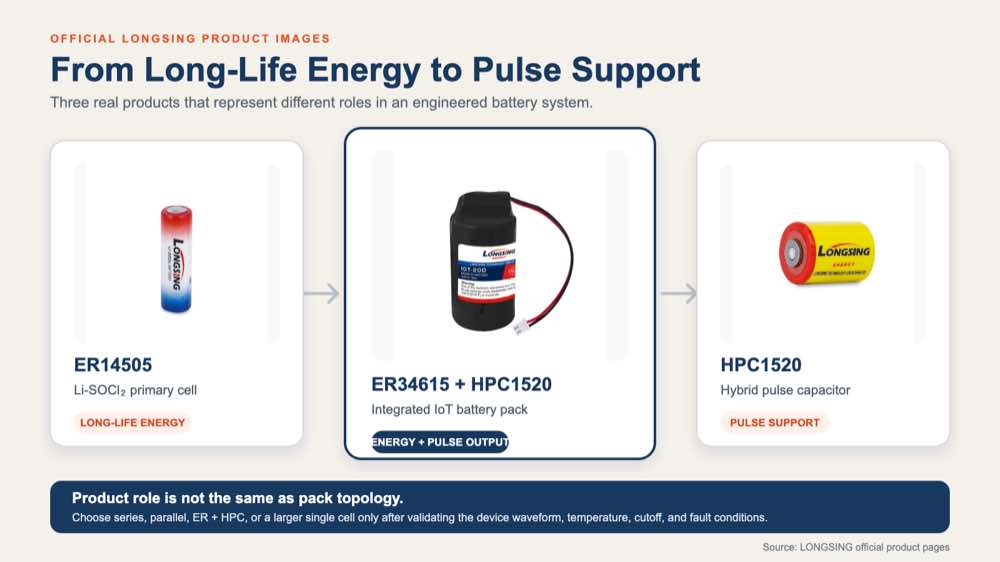
A productive review starts with the device’s measured current waveform and voltage limits. Service life, cell temperature, available space, environment, shipping form, and target markets complete the picture. With those inputs, the team can compare chemistry, cell format, topology, protection, and mechanical integration before tooling or compliance work begins.
Transport needs to enter the project early, particularly when a single-cell prototype becomes a multi-cell battery or the shipping configuration changes. LONGSING’s lithium battery transportation overview is a useful starting point; the current regulations, test laboratory, carrier, and destination requirements determine the final plan.
12. Conclusion
Series is a voltage decision; parallel is a capacity and current-sharing decision. Series-parallel does both. None of them is simply a multiplier applied to a cell datasheet. The useful result is set by the weakest series cell, the least-balanced parallel branch, and the voltage the equipment actually needs under load.
Cell consistency, protection, traceability, and device testing remain necessary even when every individual cell has passed its own qualification. The final question is practical: will this pack complete the required function after storage, at temperature, near end of life, and during the worst credible fault?
The correct primary battery architecture is the one that maintains the required voltage and energy throughout the real service life—including the worst load, temperature, fault and end-of-life conditions.
Developing a Custom Primary Lithium Battery Pack?
Send LONGSING the voltage limits, measured current waveform, pulse timing, temperature range, life target, available space, connector details, environment, replacement plan, and target markets. That information is enough to begin comparing cell and pack options before samples are built and tested in the device.
Frequently Asked Questions
Click to explore more information about primary batteries in series and parallel
1. Can primary lithium batteries be connected in series?
Yes. Series connection is used to raise pack voltage, but the cells must be compatible and matched. The design also needs a cutoff and protection strategy that prevents the weakest cell from being forced into reversal. Ah capacity remains approximately that of one cell.
2. Can primary lithium batteries be connected in parallel?
Yes, in an engineered pack. Parallel connection keeps approximately one-cell voltage while increasing theoretical capacity and current capability. Unequal voltage or resistance can cause poor current sharing or cross-current, so direct paralleling should not be approved from matching data alone.
3. Does connecting batteries in series increase capacity?
It increases nominal energy by increasing voltage, but it does not add Ah capacity. A series string of matched cells has approximately the Ah rating of one cell. Usable energy may be lower once loaded voltage, temperature, cutoff, and the weakest cell are considered.
4. Does connecting batteries in parallel increase voltage?
No. Nominal voltage remains approximately that of one cell. Ideal Ah capacity increases, but real performance depends on branch resistance, temperature, matching, interconnects, protection losses, and the device cutoff.
5. What happens if one primary cell in a series pack becomes depleted first?
The other cells may continue forcing current through it after its voltage has collapsed. That can drive the weak cell into reversal. Pack voltage alone may hide the problem, which is why weak-cell testing and individual cell-voltage measurements matter.
6. Why can current flow between parallel primary cells?
Parallel branches share the same terminals. A difference in open-circuit voltage creates a path from the higher-voltage branch into the lower one. Resistance, temperature, age, state of discharge, and storage history also affect how load current divides.
7. Do primary lithium battery packs need a BMS?
They may need protection or monitoring, but “BMS” does not define the required functions. Specify fusing, current limiting, reverse-current blocking, branch isolation, thermal protection, cutoff, or monitoring directly. Primary packs are not managed like rechargeable lithium-ion packs.
8. What information should an OEM provide for a custom primary battery pack?
Provide voltage limits, a measured current waveform, pulse timing, life target, operating and storage temperatures, available space, connector details, environment, replacement method, shipping configuration, target markets, standards, and forecast volume.
References
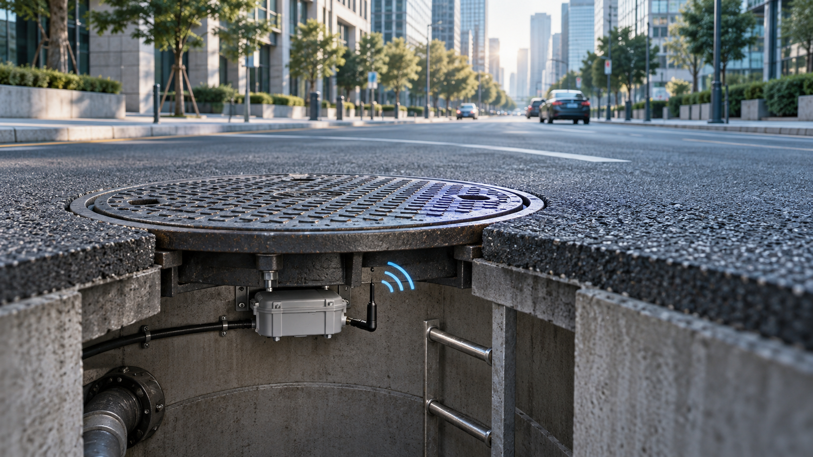
How to Choose the Best Smart Manhole Cover Sensor Battery
A smart manhole cover sensor may spend most of its life doing very little. For long periods, the dev

4 Proven Ways for Your Smart Parking Sensor Battery
Smart parking sensor battery guide covering Li-SOCl2, LoRaWAN and NB-IoT pulse loads, passivation, l

How to Choose Lithium D Batteries: ER34615 Specs, Life & Application
Key Takeaways Lithium D batteries provide higher voltage, long life, and wide temperature tolerance