

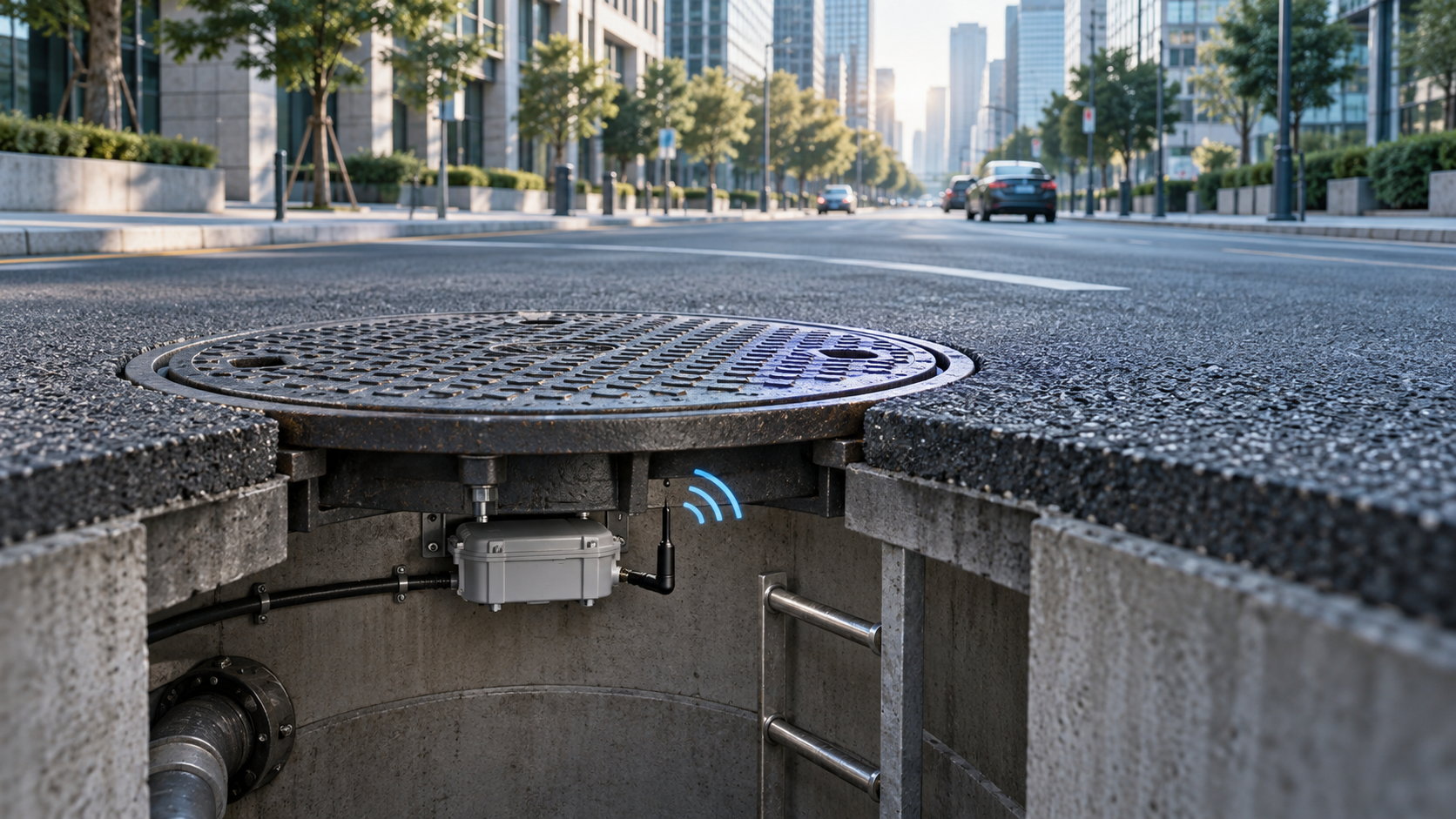
How to Choose the Best Smart Manhole Cover Sensor Battery
A smart manhole cover sensor may spend most of its life doing very little.
For long periods, the device can remain in a low-power state, waking only to sample sensors or send a scheduled status report. But if the cover is moved, opened or tampered with, the same device may suddenly need to wake, process the event and transmit an alarm.
That creates two very different battery requirements.
The battery must store enough energy for years of unattended operation, while still maintaining sufficient voltage during short wireless and alarm events.
For an underground device that is inconvenient to access, getting only one side of that calculation right is not enough.
A smart manhole cover sensor battery must be sized twice: once for the years it spends waiting, and again for the seconds when it wakes up and communicates.
Featured Snippet: What Battery Is Suitable for a Smart Manhole Cover Sensor?
Li-SOCl₂ primary lithium batteries are often suitable for smart manhole cover sensors because they combine high stored energy with low self-discharge for long-term IoT operation. However, the correct battery depends on sleep current, wireless transmission current and duration, reporting frequency, alarm events, temperature, minimum system voltage and required service life. Applications with demanding pulse loads may also require a pulse-support architecture such as ER + HPC.
Table of Contents
1. Why Smart Manhole Cover Sensors Create a Two-Part Battery Problem
A smart manhole cover sensor combines an extremely low long-term average load with short periods of much higher activity.
Most of the lifetime may be spent sleeping. Yet the battery still needs to support sensing, processing, network activity and alarm transmission whenever the device wakes.
That means battery selection requires two separate calculations:
- Long-term energy requirement
- Short-duration pulse-power requirement
Treating both as a single average-current number can hide important design risks.
Most of the Lifetime Is Spent Waiting
A simplified operating sequence may look like:
Deep Sleep
→ Sensor Sampling
→ MCU Wake-Up / Processing
→ Wireless Communication
→ Return to Sleep
An abnormal event may follow a different path:
Movement / Opening / Tilt Event
→ Immediate Wake-Up
→ Alarm Processing
→ Wireless Transmission
→ Retry or Confirmation Where Required
→ Return to Sleep
The actual current and duration of each state depend on the hardware and firmware.
This is why an OEM should not describe the battery requirement only as:
“The average current is very low.”
For battery engineering, the important input is the current-versus-time profile of the complete operating cycle.
Lifetime Energy and Pulse Power Are Different Requirements
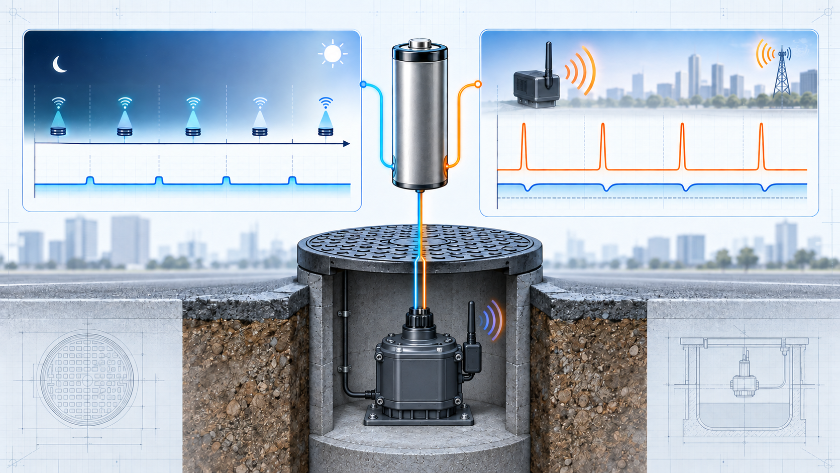
The distinction between energy and power is the central battery-design issue in this application.
| Design Question | Lifetime Energy Requirement | Pulse-Power Requirement |
|---|---|---|
| Main question | How much energy must the sensor store for the full deployment interval? | Can the battery maintain sufficient voltage during wireless and alarm events? |
| Main unit | Ah / Wh over months or years | A / W over milliseconds or seconds |
| Main loads | Sleep current, sensing, scheduled reports, network maintenance | Radio startup, TX/RX, alarm transmission, retries |
| Important battery factor | Nominal and usable capacity, self-discharge | Internal impedance, passivation, pulse duration, loaded voltage |
| Temperature effect | Changes self-discharge and long-term usable energy | Changes impedance and voltage sag |
| Network effect | More reports and retries increase cumulative energy use | Poor coverage may increase transmission duration or repetition |
| Critical system input | Required service interval and total duty cycle | Minimum system voltage and real current waveform |
| Typical failure mode | Battery reaches end of usable energy earlier than expected | Battery still contains capacity but voltage falls below the electronics’ minimum requirement |
| Design output | ER cell energy / size selection | Standalone ER validation or ER + HPC evaluation |
The two columns should be evaluated together.
A battery can pass the lifetime-energy calculation and still fail during an alarm transmission.
It can also provide excellent pulse capability but contain too little energy for the target deployment interval.
Why Average Current Alone Is Not Enough
A common first estimate is:
Estimated Lifetime ≈ Battery Capacity ÷ Average Current
This can be useful as an early calculation, but it is not a complete service-life model.
For an underground wireless sensor, the result can also be influenced by:
- Battery self-discharge
- Wireless protocol overhead
- Network retries
- Signal conditions
- Li-SOCl₂ passivation
- Temperature history
- Minimum system voltage
- Loaded-voltage drop
- Battery aging
- Design reserve
A better starting point is to build the load budget by operating state:
Qtotal = Σ(I × t × number of events)
and then account separately for calendar losses and battery limitations.
The practical conclusion is simple:
The battery must survive both the years spent sleeping and the seconds spent communicating.
2. What Determines Battery Life in NB-IoT and LoRaWAN Manhole Sensors?
Wireless communication can dominate the active-energy budget of a smart manhole sensor even when it occupies only a small fraction of the total operating time.
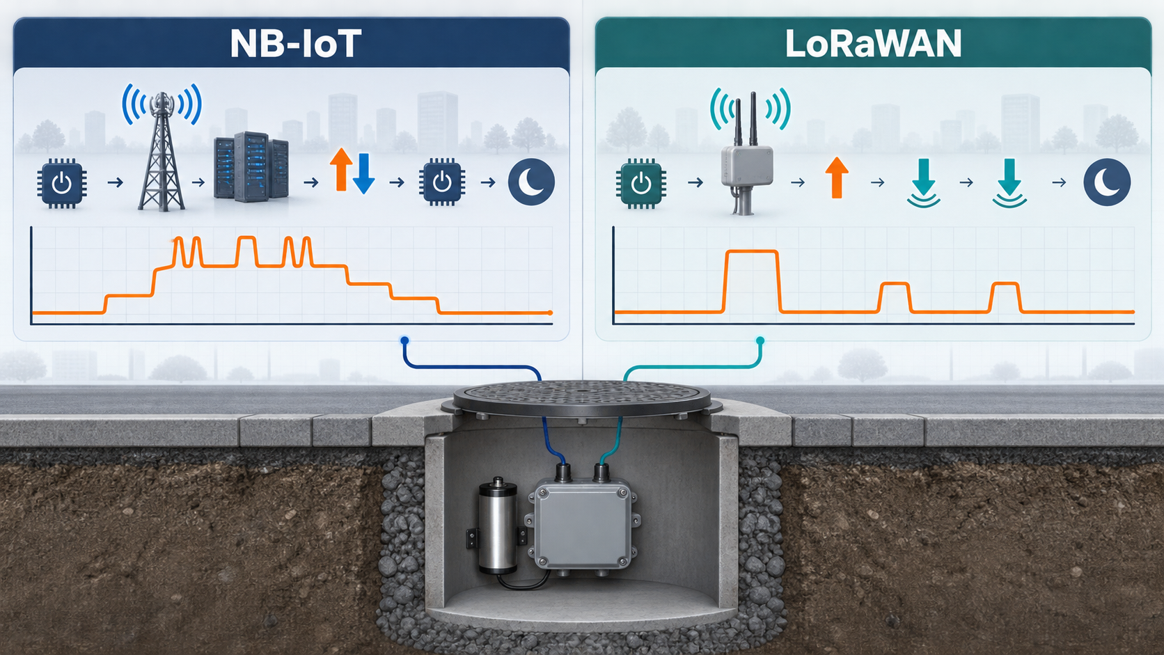
NB-IoT and LoRaWAN can both support low-duty-cycle sensor applications, but their communication sequences are different. The lifetime model should follow the actual wireless architecture rather than using one generic “radio current.”
NB-IoT Energy Is More Than TX Current
An NB-IoT communication event may contain more than a short uplink burst.
Depending on the modem, firmware and network configuration, it may include:
- Modem wake-up
- Network synchronization
- Connection establishment
- Uplink transmission
- Downlink reception
- Network inactivity time
- Connection release
- Return to Power Saving Mode
- Retries or coverage repetitions
For this reason, the useful battery parameter is often:
Energy per complete communication event
rather than only the maximum transmitter current.
NB-IoT devices can use mechanisms such as Power Saving Mode (PSM) to reduce power consumption between communication events. Release Assistance Indication can also help some devices return to lower-power operation sooner when the network and modem support it. [1][2]
These features can materially affect lifetime, but they are system and network dependent.
They should not be assumed from the label “NB-IoT” alone.
Underground RF Conditions Can Change Event Energy
An underground installation introduces another variable: the radio environment.
The actual communication energy can depend on:
- Installation depth
- Manhole-cover material
- Antenna position
- Surrounding structures
- Network coverage
- Interference
- Retransmissions
- Coverage-enhancement repetitions
Poorer communication conditions can increase transmission time, power or repetition count in some cellular deployments. [1][2]
This does not mean every underground NB-IoT sensor has poor coverage.
It means the actual installation environment should be represented in battery validation.
For a manhole-monitoring system:
RF conditions are part of the battery requirement.
LoRaWAN Battery Use Depends on the Device Class and Airtime
LoRaWAN follows a different operating pattern.
For a Class A device, a communication cycle typically includes:
Uplink Transmission
→ RX1 Window
→ RX2 Window
→ Return to Sleep
Class A is designed for low-power end devices because receive activity is tied to uplink events. Class B introduces additional scheduled receive opportunities, while Class C keeps the receiver active for much more of the time and therefore has a substantially different power profile. [3]
For a long-life manhole sensor, the LoRaWAN class should therefore be included in the battery model.
Time-on-air also matters.
A longer radio transmission consumes more energy even if peak TX current remains unchanged.
Factors such as:
- Data rate
- Spreading factor
- Payload length
- TX power
- Retransmission behavior
- Adaptive Data Rate
can influence the energy required for one communication event. [4]
So the battery question is not only:
“How often does the device transmit?”
It is also:
“How long does each wireless event last?”
NB-IoT vs LoRaWAN Battery-Model Considerations
| Battery Design Factor | NB-IoT | LoRaWAN Class A |
|---|---|---|
| Long sleep mechanism | PSM / network-configured low-power operation | Application-controlled sleep between events |
| Typical event sequence | Wake, network activity, TX/RX, release, return to low power | Uplink, RX1, RX2, sleep |
| Coverage impact | Repetitions, TX power and connection duration may increase | Lower data rate can increase time-on-air |
| Network configuration | Operator timers and RAI support may influence energy | ADR and network settings influence airtime / TX behavior |
| Battery concern | Variable event energy + significant transient load | TX pulse + airtime + receive-window consumption |
| OEM input required | Real modem current-versus-time waveform | Real radio current profile and data-rate behavior |
Neither protocol is automatically the “better battery choice” in every installation.
The correct model should use the actual network and hardware implementation.
Scheduled Reports and Alarm Events Should Be Modeled Separately
A smart manhole cover sensor usually has at least two different event categories.
Normal Operation
This may include:
- Heartbeat messages
- Scheduled sensor reports
- Status updates
- Network maintenance
- Periodic synchronization
These events can be modeled from a known reporting interval.
Alarm Operation
This may include:
- Cover opening
- Abnormal tilt
- Displacement
- Tampering
- Repeated alarm transmission
- Confirmation or retry messages
Alarm activity is less predictable.
Instead of assuming no alarms, OEMs can develop at least two operating scenarios:
Normal-Year Scenario
and
High-Event Scenario
This produces a more realistic lifetime range than a single idealized value.
3. When Is a Li-SOCl₂ Battery Enough—and When Should ER + HPC Be Evaluated?
Li-SOCl₂ batteries are widely considered for long-life unattended electronics because they can provide high stored energy with very low self-discharge.
For smart manhole monitoring, however, the long-term energy requirement is only half of the selection problem.
Wireless and alarm events must also be supported at an acceptable loaded voltage.
Why Li-SOCl₂ Fits Long-Life Underground IoT
Li-SOCl₂ primary lithium batteries can be attractive for remote IoT systems because of characteristics such as:
- High stored energy
- High energy density
- Low self-discharge
- Stable long-duration primary-battery operation
- 3.6 V-class nominal architecture
These characteristics make the chemistry relevant to devices expected to remain unattended for long periods.
LONGSING Website A currently provides a dedicated Li-SOCl₂ Battery range as part of its primary-lithium product portfolio.
However:
Li-SOCl₂ should primarily be viewed as the long-term energy reservoir. High pulse capability should not be assumed from chemistry alone.
Wireless pulse performance must still be evaluated for the actual application. [5]
Passivation Helps Long Storage but Changes First-Pulse Behavior
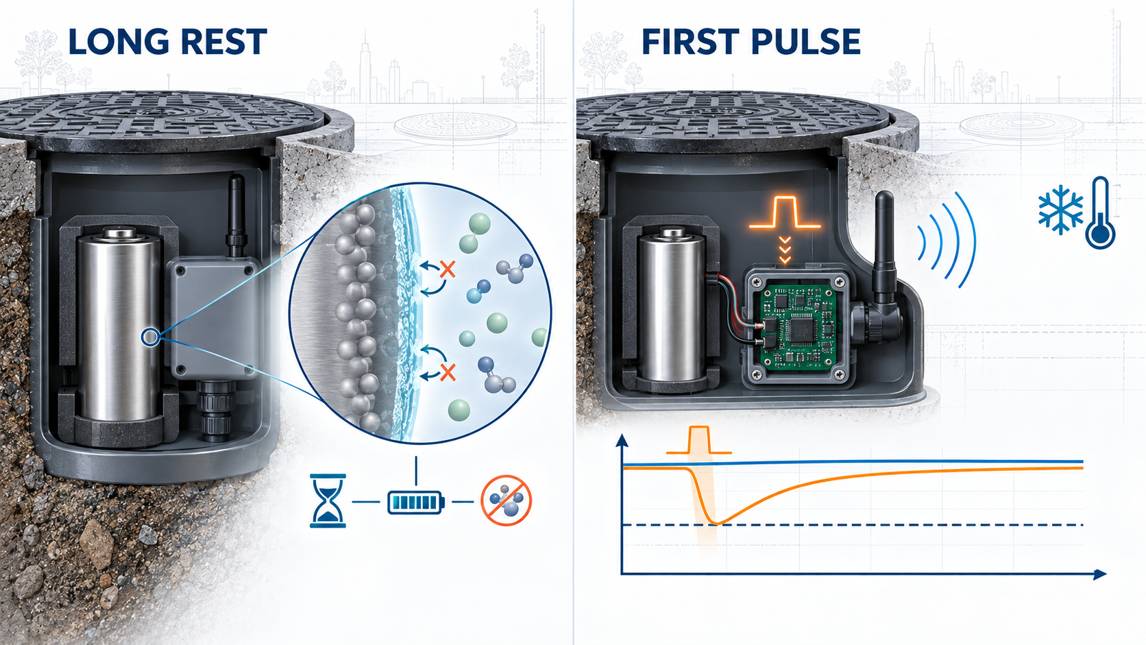
One of the defining characteristics of Li-SOCl₂ chemistry is passivation.
During storage and low-current operation, a passivation layer forms at the lithium surface. This suppresses parasitic chemical reactions and contributes to the chemistry’s very low self-discharge and long storage capability.
But the same layer can temporarily increase internal resistance.
When a cell that has been resting for a long time is suddenly placed under a higher load, the initial voltage can drop before recovering as the passivation layer responds to the load. [6]
That means passivation is not simply a battery defect.
It is part of the same electrochemical behavior that supports long-term storage performance.
The engineering issue is whether the application can tolerate the resulting voltage delay.
For a smart manhole sensor, an important worst-case test may be:
The first alarm transmission after a long idle period, at an unfavorable temperature and late in the battery’s service life.
Testing only a fresh cell at room temperature may not reveal that condition.
Why Loaded Voltage Matters More Than a Headline Pulse-Current Number
A useful first-order approximation is:
Vload ≈ VOC − I × Rtotal
where Rtotal includes more than cell impedance.
The complete electrical path may include:
Battery → Tabs / Leads → Connector → Protection Components → PCB → Radio / Modem
The critical condition is:
Vload ≥ Vsystem,min
If the supply falls below the modem or MCU minimum voltage during a transmission event, the result may be:
- Modem reset
- MCU brownout
- Failed uplink
- Lost alarm message
even if the battery still contains substantial chemical capacity.
This is why battery capacity should be evaluated as usable capacity above the actual system voltage threshold, not simply nominal Ah.
Pulse duration also matters.
A current pulse lasting milliseconds and the same current lasting several seconds impose very different requirements.
Battery validation should therefore use the real:
- Peak current
- Pulse duration
- Event sequence
- Rest interval
- Temperature
- Battery age
- Minimum operating voltage
ER26500 vs ER34615: Start With Energy and Space
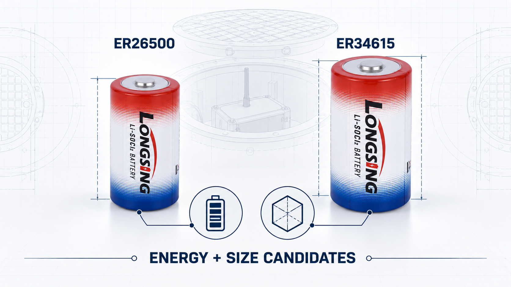
LONGSING Website A currently publishes several Li-SOCl₂ ER sizes that can serve as candidate energy reservoirs. [7]
Two relevant examples are:
| Candidate | Current LONGSING Published Nominal Data | Engineering Interpretation |
|---|---|---|
| ER26500 | 3.6 V / 8.5 Ah | Candidate where the required lifetime energy and available enclosure volume fit this size |
| ER34615 | 3.6 V / 19 Ah | Candidate where a larger long-term energy reserve is required and the enclosure can accommodate it |
These published capacities do not determine the service life of a manhole sensor by themselves.
The selection sequence should begin with:
- Calculate the complete lifetime energy requirement.
- Add appropriate design and aging reserve.
- Check available battery space.
- Identify an ER capacity candidate.
- Test the real wireless and alarm waveform.
This leads to an important distinction:
ER26500 vs ER34615 begins primarily as an energy-and-size decision. ER + HPC begins primarily as a pulse-power decision.
When ER + HPC Becomes Worth Evaluating
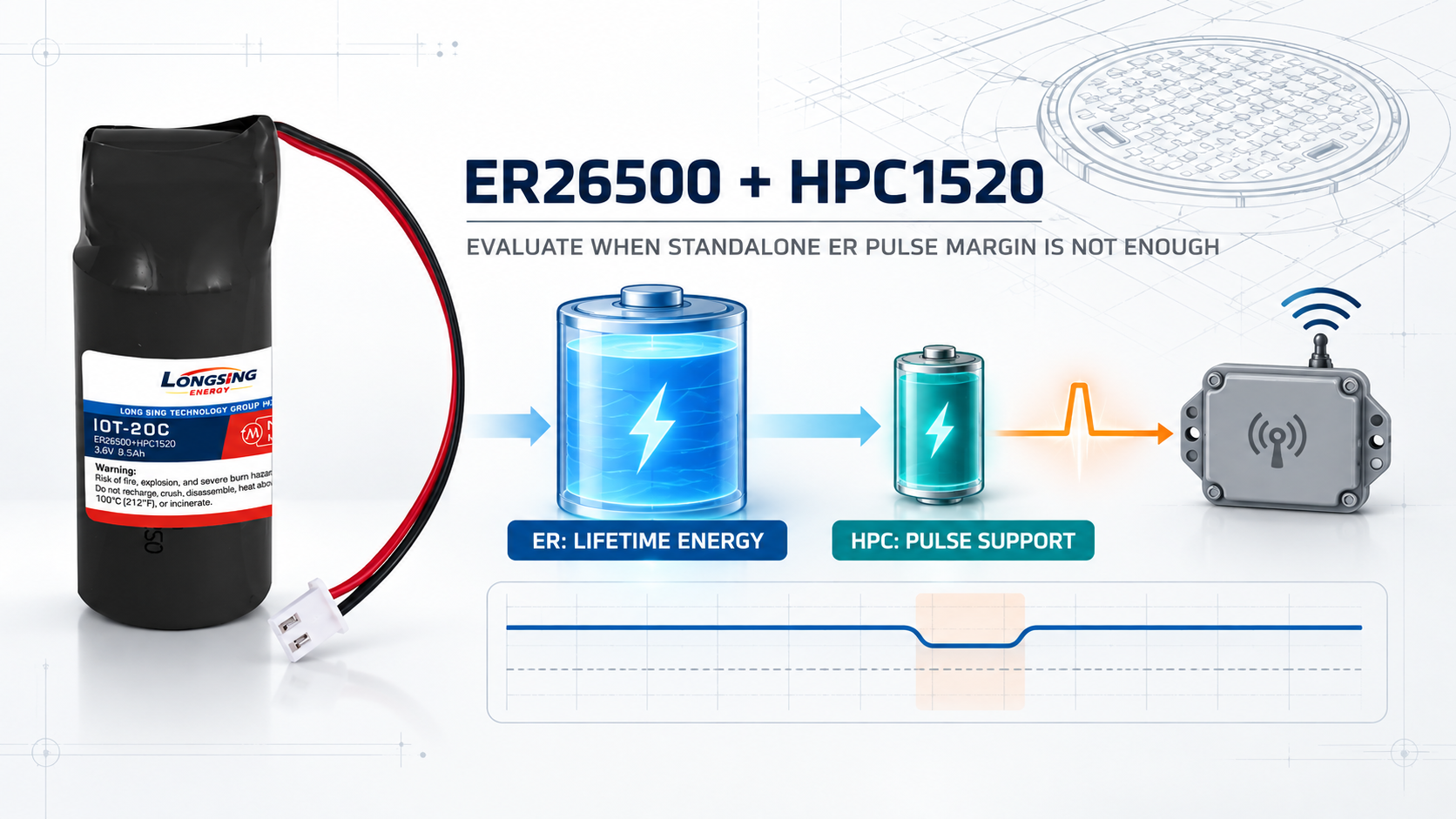
A standalone ER cell may be suitable when it can satisfy both:
- The long-term energy requirement
- The loaded-voltage requirement during the worst pulse event
If the ER cell has enough lifetime energy but cannot maintain sufficient voltage during the radio or alarm waveform, a pulse-support architecture becomes worth evaluating.
The decision path can be represented as:
Calculate Lifetime Energy
↓
Select an ER Capacity Candidate
↓
Test the Actual Wireless / Alarm Waveform
↓
Compare Loaded Voltage With Vsystem,min
↓
Standalone ER Passes?
→ Yes: Continue system validation
→ No: Evaluate ER + HPC
In an ER + HPC architecture:
ER cell
→ provides long-term stored energy
while:
HPC pulse-support element
→ helps support short-duration high-power events
LONGSING currently offers ER + HPC configurations such as ER26500 + HPC within Website A.
However, published pulse-current numbers must be interpreted together with their test conditions.
For example, LONGSING’s ER + HPC product data defines pulse capability using conditions such as:
1 s pulse at a 3.0 V termination condition
A published pulse-current figure under that test condition does not automatically prove compatibility with:
- A longer pulse
- Repeated alarm transmissions
- A higher system cutoff voltage
- Low-temperature operation
- A partially aged battery
- A specific NB-IoT modem waveform
The actual device should still be validated.
Temperature Changes Both Lifetime and Pulse Margin
Temperature affects the two battery budgets differently.
Low Temperature
Lower temperature can increase effective impedance and reduce loaded-voltage margin during a pulse.
The cell may still contain energy, but the application may be unable to use it if voltage falls below the system threshold.
So it is more accurate to say:
Low temperature can reduce the energy and power practically available to the device under load.
rather than saying that cold simply “removes battery capacity.”
High Temperature
Higher temperatures can accelerate long-term chemical losses and can also affect passivation behavior.
For a multi-year deployment, the temperature history of the battery is therefore relevant to lifetime prediction. [6]
The useful engineering input is not only:
minimum / maximum operating temperature
but:
the expected temperature profile across the service life.
Underground Environmental Protection Is a System Requirement
Smart manhole monitoring also introduces environmental concerns such as:
- Humidity
- Condensation
- Water ingress
- Corrosion
- Contamination
These are primarily system-integration issues involving:
- Enclosure sealing
- PCB protection
- Cable glands
- Connectors
- Battery mounting
- Environmental validation
Selecting a Li-SOCl₂ cell does not make the complete sensor waterproof.
Unless a specific battery or battery assembly has a verified ingress-protection rating, claims such as “waterproof battery” or “IP68 battery” should not be inferred from the application environment.
4. What Should OEMs Specify Before Selecting a Smart Manhole Cover Sensor Battery?
A useful battery RFQ should describe the complete operating profile.
For example:
“We need an ER26500 for an NB-IoT manhole sensor.”
does not yet contain enough information to confirm the battery architecture.
The supplier needs to understand both the years-long energy budget and the short communication events.
Electrical and Lifetime Inputs
OEMs should provide:
- Nominal operating voltage
- Minimum system voltage
- Deep-sleep current
- MCU standby current
- Sensor current
- Required deployment interval
- Scheduled reporting interval
- Number of sensor measurements
- Expected alarm-event frequency
- End-of-life reserve requirement
This information defines the long-term energy requirement.
Wireless Load Inputs
Provide:
- Wireless protocol
- NB-IoT / LoRaWAN / other radio technology
- Modem or radio model
- TX current waveform
- RX current
- Transmission duration
- Receive-window duration
- Retry behavior
- Repetition behavior
- Normal reporting sequence
- Alarm reporting sequence
- Expected RF coverage conditions
Simply saying:
“NB-IoT sensor”
is not enough for reliable battery selection.
Two NB-IoT devices with different network configurations and signal conditions may have substantially different event-energy profiles.
Mechanical and Environmental Inputs
Provide:
- Maximum battery length
- Maximum diameter
- Available enclosure volume
- Installation orientation
- Termination or connector requirements
- Expected battery temperature range
- Typical temperature profile
- Humidity / condensation conditions
- Service-access constraints
The environmental enclosure should be treated as part of the system design rather than relying on the cell itself for ingress protection.
Battery Validation Inputs
The OEM should also define the conditions under which battery performance must be verified.
Useful validation cases include:
- Minimum acceptable loaded voltage
- Fresh-cell wireless event
- Partially discharged battery
- Long-idle first-pulse event
- Low-temperature transmission
- Repeated alarm sequence
- Poor-coverage communication event
- End-of-life pulse event
These tests help determine whether a standalone ER cell provides adequate voltage margin or whether a pulse-support architecture should be evaluated.
Smart Manhole Cover Sensor Battery Specification Checklist
| OEM Input | Why the Battery Supplier Needs It |
|---|---|
| Sleep current | Determines continuous multi-year energy consumption |
| Scheduled reporting interval | Determines recurring communication energy |
| Alarm-event assumption | Adds uncertain but potentially important lifetime consumption |
| TX / RX waveform | Defines transient power requirement |
| Pulse duration | Influences voltage drop and pulse-support sizing |
| Minimum system voltage | Defines how much stored battery energy is actually usable |
| Wireless protocol | Changes the communication sequence and energy model |
| RF coverage condition | Can change TX power, repetitions and event duration |
| Operating-temperature profile | Affects self-discharge, impedance and pulse response |
| Target service interval | Establishes the required long-term energy reserve |
| Battery-space envelope | Determines which ER sizes and architectures can physically fit |
| Environmental enclosure | Defines system sealing and installation requirements |
Where LONGSING Fits
LONGSING Website A provides primary-lithium battery architectures relevant to long-life wireless sensor development.
Its current product directions include:
- Li-SOCl₂ / ER Batteries
- ER26500
- ER34615
- ER + HPC hybrid battery configurations
- Broader Primary Lithium Battery solutions
These should be treated as candidate battery architectures rather than fixed smart-manhole-cover solutions.
A practical selection sequence is:
Device Sleep + Sensor Load
↓
Scheduled + Alarm Communication Energy
↓
Required Service Interval
↓
Lifetime Energy Requirement
↓
ER Cell Size Candidate
↓
Real Wireless Pulse Test
↓
Minimum Loaded-Voltage Check
↓
Temperature + Passivation Validation
↓
Standalone ER or ER + HPC Decision
↓
System-Level Environmental Validation
For another example of how cellular IoT communication can influence primary-lithium battery selection, see LONGSING’s NB-IoT Water Meter Battery engineering guide.
The battery should ultimately be selected from the actual load profile—not simply from the application name.
Conclusion
A reliable smart manhole cover sensor battery cannot be selected from average current or nominal Ah alone.
The battery must contain enough energy for years of sleep, sensing and scheduled communication while also maintaining sufficient voltage during wireless and alarm pulses. NB-IoT or LoRaWAN behavior, RF coverage, Li-SOCl₂ passivation, temperature, system cutoff voltage and battery aging all influence the result.
For long-life underground IoT, lifetime energy and pulse power should be engineered separately—and validated together.
Developing a Smart Manhole Cover or Underground IoT Monitoring Device?
For a meaningful primary-lithium battery evaluation, prepare:
- System operating voltage
- Minimum system voltage
- Deep-sleep current
- Sensor / MCU current
- Wireless protocol
- TX and RX current profile
- Transmission duration
- Scheduled reporting interval
- Alarm-event assumptions
- Expected RF coverage
- Operating-temperature profile
- Required service interval
- Available battery dimensions
- Termination / connector requirements
- Environmental and enclosure conditions
These inputs allow the long-term energy requirement and pulse-power requirement to be evaluated separately before selecting a standalone ER or ER + HPC battery architecture.
Frequently Asked Questions About Smart Manhole Cover Sensor Batteries
Click to explore more information about smart manhole cover sensor batteries
What battery is used in a smart manhole cover sensor?
Smart manhole sensors can use primary lithium batteries such as Li-SOCl₂ ER cells when the device requires long unattended operation and very low average power. The correct cell size and architecture depend on the sensor’s energy budget, wireless load, temperature, available space and minimum system voltage.
Why is Li-SOCl₂ suitable for smart manhole cover monitoring?
Li-SOCl₂ batteries provide high stored energy and low self-discharge, which can suit devices expected to remain in service for long periods without charging. However, wireless pulse performance must be evaluated separately because long-life energy capability does not automatically guarantee sufficient transient loaded voltage.
How do you calculate battery life for a smart manhole sensor?
Start by calculating charge or energy consumption for deep sleep, sensing, MCU operation, scheduled wireless reports and expected alarms. Then account for self-discharge, temperature, network behavior, system cutoff voltage, battery aging and reserve. Simply dividing nominal Ah by average current can overestimate practical service life.
Why is average current not enough to select an IoT sensor battery?
A manhole sensor may draw very little current while sleeping but much more when the radio wakes and transmits. A battery may contain sufficient total energy yet experience excessive voltage drop during a communication pulse. Both lifetime energy and transient power therefore need to be evaluated.
How does NB-IoT affect smart manhole cover battery life?
NB-IoT energy consumption depends on more than transmitter current. Network synchronization, connection time, TX/RX activity, PSM configuration, network release, retries, repetitions and RF coverage can all affect energy per communication event. The real modem current waveform should be used for battery-life modeling.
How does LoRaWAN affect manhole sensor battery consumption?
For a LoRaWAN Class A device, energy is used during uplink transmission and the following receive windows before the device returns to sleep. Data rate, time-on-air, TX power, ADR behavior, reporting frequency and retransmissions can all influence total consumption.
When does a smart manhole sensor need an ER + HPC battery?
ER + HPC is worth evaluating when a Li-SOCl₂ ER cell provides sufficient long-term energy but cannot maintain adequate voltage during the device’s worst wireless or alarm pulse. The decision should be based on the real waveform, pulse duration, temperature, minimum system voltage, passivation condition and battery state of life.
What information should an OEM provide when selecting a manhole sensor battery?
Provide the operating-voltage range, minimum system voltage, sleep current, sensor load, TX/RX current waveform, pulse duration, wireless protocol, reporting interval, alarm assumptions, RF conditions, temperature profile, required service interval, battery-space limitation and environmental requirements.
References
[2] u-blox — SARA-N2 NB-IoT Application Development Guide. ↪
[3] LoRa Alliance — LoRaWAN Device Classes and Link-Layer Architecture. ↪
[4] LoRa Alliance — Developing LoRaWAN Devices / ADR Technical Guidance. ↪
[5] Texas Instruments — How to Extend Operating Time of a Li-SOCl₂ Powered System. ↪
[6] Saft — Li-SOCl₂ Passivation, Lifetime and Pulse-Performance Technical Resources. ↪
[7] LONGSING Website A — Li-SOCl₂, ER26500, ER34615 and ER + HPC Product Information. ↪

Lithium D Batteries for Industrial Applications: Specifications, Lifespan, and OEM Solutions
Imagine your critical industrial equipment suddenly fails because of a dead battery. Your operations

Lithium Primary Batteries: Types, Performance, and Selection Guide
Lithium primary batteries serve as the critical power backbone for long-term autonomous systems wher

Continuous Monitoring: How to Prevent Battery Failure in Toxic Gas Monitor
Every year, industrial accidents happen because gas detectors fail at critical moments. The root cau