

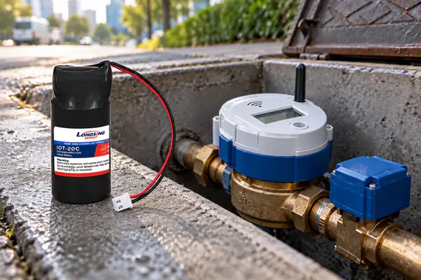
9 Reliable Ways to Size Your NB-IoT Water Meter Battery
An NB-IoT water meter battery may support years of very low-current operation, yet an NB-IoT communication event or motorized valve operation can create a much higher short-duration load.
That makes battery sizing a two-part engineering problem. The meter needs enough stored energy for the required service life, but the power system must also maintain sufficient voltage during its most demanding events.
A battery selected only from nominal amp-hour capacity can therefore look adequate on paper while still causing modem resets, MCU brownouts or failed valve operations in the field.
Featured Snippet: How Do You Size a Battery for an NB-IoT Smart Water Meter?
Size an NB-IoT water meter battery in two stages. First, calculate the lifetime charge and energy requirement from sleep current, sensing, communication events, valve operations, transmission frequency, self-discharge and service-life reserve to select a candidate ER cell. Then verify the worst-case pulse waveform, minimum system voltage, temperature and passivation behavior. If a standalone Li-SOCl₂ cell cannot maintain sufficient voltage, evaluate HPC pulse support.
Table of Contents
1. How Do You Calculate the Lifetime Energy Requirement of an NB-IoT Water Meter?
An NB-IoT water meter battery should be sized from the real operating duty cycle rather than one assumed average-current value.
NB-IoT devices can move between deep low-power states and much more energy-intensive communication states. Power Saving Mode (PSM) and extended Discontinuous Reception (eDRX) are specifically intended to reduce Mobile IoT power consumption, but their configuration and network behavior still affect the complete long-term energy budget. GSMA Mobile IoT energy-efficiency guidance provides useful background. [1]
Break the Meter Load Into Operating States
A practical battery model should separate the major operating states of the meter, such as:
- Sleep / PSM
- MCU wake-up
- Meter measurement
- Sensor operation
- Network registration and synchronization
- NB-IoT uplink
- Downlink or acknowledgment
- Communication inactivity periods
- Valve actuation, where applicable
- Display, diagnostics or other auxiliary loads
Do not use a single “average current” unless it has already been derived from the complete measured duty cycle.
A meter transmitting once per day can have a very different lifetime energy requirement from a meter transmitting hourly, reconnecting frequently or operating under poor radio conditions.
Calculate Each Event From Current and Time
For applications operating from a relatively stable battery voltage, charge consumption is often a convenient first calculation.
For one event:
Qevent (mAh) = ∫ I(t)dt / 3600
For a waveform approximated by several constant-current stages:
Qevent = (I₁t₁ + I₂t₂ + … + Iₙtₙ) / 3600
where current is in mA and time is in seconds.
A daily charge budget can then be expressed as:
Qday = Qsleep + NTX × QTX + Nmeasure × Qmeasure + Nvalve × Qvalve + Qother
The first-order application load over the required service period is:
Qload = Qday × 365 × Years
This calculation produces a charge budget, not yet the final required nominal battery capacity.
Where system voltage changes significantly or DC/DC conversion needs to be evaluated, energy in Wh is more appropriate:
Eevent (Wh) = ∫ V(t) × I(t)dt / 3600
using voltage in volts, current in amperes and time in seconds.
This distinction matters because battery lifetime is ultimately governed by both available charge and the voltage at which that charge remains usable by the meter.
The Application Load Is Not the Final Battery Size
After calculating the expected meter load, engineers still need to account for factors such as:
- Cell self-discharge
- Expected temperature history
- DC/DC conversion losses
- Installation and commissioning activity
- Network retries
- Longer-than-expected communication sessions
- Valve operations
- Production variation
- Service-life reserve
- End-of-life voltage margin
LONGSING currently publishes a self-discharge characteristic of less than 1% per year at 20°C for its ER-series Li-SOCl₂ products. This is a useful product specification, but it should not be converted into an exact rule such as “15 years means exactly 15% capacity loss.”
Temperature, storage history, actual load and cell condition all matter.
Use a validated self-discharge allowance based on the selected ER cell and the meter’s expected field temperature profile.
Why NB-IoT Communication Energy Is More Than the RF Transmit Burst
One communication event can contain much more than the payload transmission itself.
Depending on the network state and configuration, the modem may consume energy during:
- Network access
- Synchronization
- Signaling
- Radio connection
- Uplink transmission
- Downlink reception
- Inactivity periods
- Retransmissions
- Coverage-enhancement repetitions
Peer-reviewed NB-IoT energy-consumption modeling shows that PSM, eDRX, communication-state transitions and repetitions can materially affect battery consumption. [2]
Measure the complete communication event at the battery terminals rather than sizing the battery from RF transmit current alone.
Poor Coverage Can Change Water Meter Battery Life
This is particularly important for smart water meters installed:
- Underground
- Inside meter pits
- Beneath metal covers
- Behind concrete
- In other weak-signal locations
Experimental NB-IoT research published in 2026 found that worsening radio conditions can increase connection duration, retransmissions and total communication energy, particularly at higher Coverage Enhancement levels. [3]
A realistic battery-life model should therefore evaluate at least:
Normal network condition
and
Specified weak-network condition
rather than assuming every field transmission has laboratory-quality coverage.
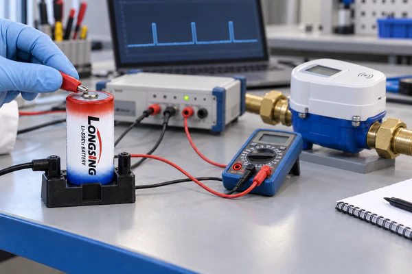
NB-IoT Water Meter Battery Lifetime Budget
| Load Component | Input Required | Sizing Method |
|---|---|---|
| Sleep / PSM | Sleep current + duration | Current × time |
| Meter measurement | Current + event duration + frequency | Events × charge/event |
| NB-IoT communication | Complete communication waveform + transmissions/day | NTX × QTX |
| Valve actuation | Actual valve waveform + expected operations | Nvalve × Qvalve |
| Other electronics | MCU, sensing, display, auxiliaries | Sum individual loads |
| Design allowance | Self-discharge, temperature, conversion loss, retries, reserve | Added after load calculation |
At the end of this stage, the engineer has an estimate of the long-term charge and energy requirement.
Only then should candidate ER cells be selected.
2. How Do You Decide Whether a Standalone Li-SOCl₂ Cell Is Enough?
Once the lifetime energy requirement is known, the engineer can identify candidate Li-SOCl₂ batteries.
However, nominal capacity alone does not determine whether an ER cell can reliably power an NB-IoT meter.
A standalone ER cell has to satisfy two requirements:
Enough lifetime energy
and
Enough loaded voltage during the worst event
Select Candidate ER Cells From the Lifetime Requirement
Current LONGSING product data publishes the following ER-series characteristics:
| LONGSING ER Cell | Nominal Voltage | Published Nominal Capacity | Published Max. Continuous Current | Published Max. Pulse Current |
|---|---|---|---|---|
| ER14505 | 3.6 V | 2.6 Ah | 50 mA | 100 mA |
| ER26500 | 3.6 V | 8.5 Ah | 100 mA | 200 mA |
| ER34615 | 3.6 V | 19 Ah | 150 mA | 300 mA |
These are published LONGSING product characteristics, not universal NB-IoT water-meter requirements.
For ER26500 and ER34615, current LONGSING datasheets also show that nominal capacity is defined under specified discharge and cutoff conditions rather than being a value available under every possible load and temperature.
Therefore, an engineer should not assume:
ER14505 = small water meter
ER26500 = standard water meter
ER34615 = long-life water meter
The calculated lifetime requirement, actual load profile, meter enclosure and voltage margin should determine which ER sizes become candidates.
Nominal Capacity Is Not the Same as Usable Meter Energy
A cell can still contain chemical capacity while being unable to maintain the voltage required by the electronics during a high-current event.
The practical requirement is:
Vload ≥ Vsystem,min
where Vsystem,min is the actual minimum operating voltage of the complete meter.
That limit can be determined by:
- NB-IoT modem requirements
- MCU minimum supply voltage
- DC/DC converter UVLO
- Sensors
- Valve driver
- System brownout or reset threshold
If battery voltage falls below that limit during transmission or valve operation, the meter can fail even when nominal capacity remains.
Remaining chemical capacity is not necessarily usable system energy.
Li-SOCl₂ Passivation Affects Pulse Response
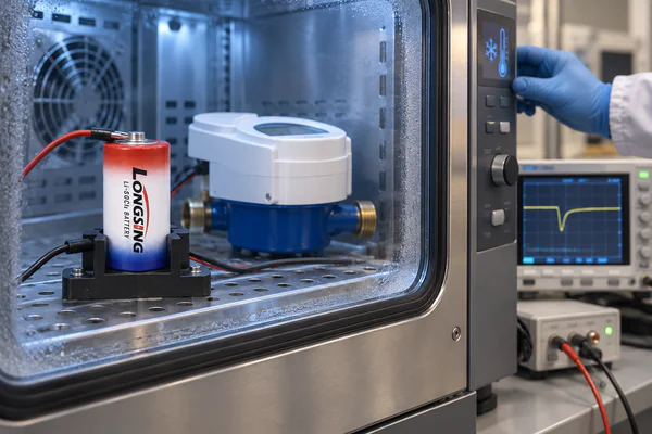
Li-SOCl₂ chemistry naturally forms a protective film on the lithium surface during storage and low-current operation.
This passivation contributes to the chemistry’s ability to limit unwanted long-term reactions, but classic electrochemical research on Li-film growth also shows that the lithium surface film grows with storage time and temperature and is associated with the well-known voltage-delay phenomenon. [4]
The practical sequence can be:
Long idle period
↓
Passivation develops
↓
A much higher load is suddenly applied
↓
Initial effective source impedance is higher
↓
Temporary voltage drop / voltage delay
A modern review of Li-SOCl₂ technology likewise identifies voltage delay and limited high-rate capability as important engineering challenges for this chemistry. [5]
Passivation should therefore not be described as simply a defect.
It is part of the electrochemical behavior associated with long-storage primary cells, but it means that pulse performance after long standby needs to be verified.
Validate the Worst-Case Event
Do not evaluate the cell only from an NB-IoT module’s nominal TX current.
A realistic worst-case event may include:
- Modem startup
- Network signaling
- RF transmission
- Retransmission
- Weak coverage
- MCU activity
- Sensor activity
- Valve operation
- Low temperature
- Extended previous standby
- Partial battery life
- End-of-life condition
Can the candidate standalone ER cell keep the complete meter above its actual minimum operating voltage during the defined worst-case waveform?
If yes, a standalone ER cell may be sufficient.
If the lifetime energy requirement is satisfied but the loaded voltage margin is not, then an ER + HPC architecture becomes worth evaluating.
NB-IoT alone does not automatically mean that an HPC is required.
3. How Should HPC Be Sized for NB-IoT and Valve Pulse Loads?
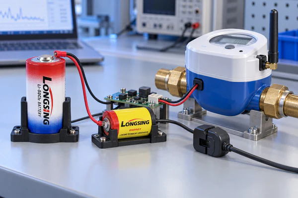
A Hybrid Pulse Capacitor should be selected because the meter requires additional transient-power capability—not simply because the product uses wireless communication.
In an ER + HPC system:
ER cell = long-term energy reservoir
HPC = rechargeable pulse-support element
Peer-reviewed work on a bobbin Li/SOCl₂ cell connected in parallel with an electrochemical capacitor demonstrated the use of the capacitor as a high-current buffer and as a way to reduce voltage-delay effects during high-current discharge. [6]
LONGSING uses the same general power architecture in its Hybrid Pulse Capacitor and IoT battery pack product families.
Do Not Add HPC Capacity Directly to ER Capacity
The HPC should not be treated as if it were simply extra primary-cell Ah.
HPC supports a high-load event
↓
its stored charge decreases
↓
the ER cell gradually replenishes it
↓
the HPC becomes available for another event
Therefore, the meter’s long-term service energy still comes primarily from the ER cell.
The HPC mainly improves:
- Pulse-current capability
- Loaded-voltage margin
- Response during sudden high-load events
Its function is fundamentally different from selecting a larger ER cell for additional lifetime energy.
Size HPC From Current, Duration and Voltage Margin
A simple first-order capacitor model helps illustrate the key variables.
The immediate voltage drop associated with equivalent series resistance can be approximated as:
ΔVESR ≈ I × ESR
The idealized capacitive voltage change can be estimated as:
ΔVC ≈ I × t / C
This gives a conceptual relationship:
ΔVtotal ≈ ΔVESR + ΔVC + other system losses
These equations explain why peak current alone cannot size the HPC.
For example:
1 A × 0.2 s
and
1 A × 5 s
have the same peak current but very different charge requirements.
However, an HPC is an electrochemical hybrid pulse device rather than an ideal linear capacitor.
These equations should therefore be treated only as first-order screening tools.
Final evaluation needs to account for:
- Actual HPC electrical characteristics
- ER/HPC current sharing
- Starting voltage
- Pulse duration
- Temperature
- Repeated events
- Recovery interval
- Interconnect resistance
- Meter minimum voltage
Valve Loads Should Be Evaluated Separately
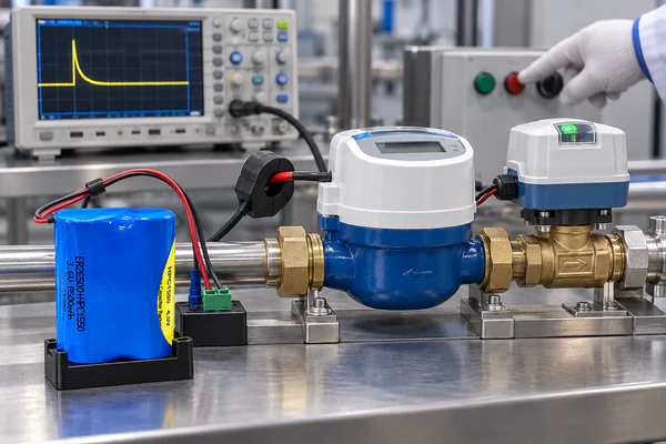
Some NB-IoT water meters also contain motorized shut-off valves.
A valve may operate only a small number of times over the meter’s service life, so its contribution to total Ah can be relatively small.
At the same time, it may be the highest-power load in the entire device.
This is exactly why lifetime energy and pulse-power sizing must remain separate.
Valve evaluation should consider:
- Motor startup current
- Running current
- Actuation duration
- End-position behavior
- Retry events
- Consecutive operations
- Simultaneous communication where applicable
LONGSING’s existing Smart Gas Meter Shut-Off Valve Battery guide discusses the energy-versus-valve-pulse distinction in more detail.
The same engineering principle applies here, but the water-meter article remains focused on the complete NB-IoT battery-sizing process.
Recovery Time Matters
After an HPC supports a high-current event, it needs time to recover energy from the ER cell.
The engineer should therefore consider event sequences such as:
TX → retry → TX
Valve operation → status transmission
Valve attempt → retry
An HPC that successfully supports one isolated laboratory pulse may not provide the same voltage margin when several high-load events occur close together.
HPC sizing should therefore include:
peak current + pulse duration + number of consecutive events + recovery interval
Use LONGSING ER + HPC Pulse Data as Screening Data
LONGSING currently publishes several ER + HPC combinations:
| Combination | Published ER Capacity | Published Maximum Pulse |
|---|---|---|
| ER14505 + HPC1520 | 2.6 Ah | 1 A |
| ER14505 + HPC1530 | 2.6 Ah | 2 A |
| ER26500 + HPC1520 | 8.5 Ah | 1 A |
| ER26500 + HPC1530 | 8.5 Ah | 2 A |
| ER26500 + HPC1550 | 8.5 Ah | 3 A |
| ER34615 + HPC1520 | 19 Ah | 1 A |
| ER34615 + HPC1530 | 19 Ah | 2 A |
| ER34615 + HPC1550 | 19 Ah | 3 A |
The important qualification is in the published table heading:
Maximum pulse current @ 1 s @ termination 3.0 V [7]
That test condition must travel with the number.
For example, a published 1 A figure does not automatically prove compatibility with:
- A 5-second valve load
- A meter requiring more than 3.0 V during the event
- Repeated transmissions
- Low-temperature operation
- End-of-life battery condition
Published pulse current is useful for preliminary architecture screening, but it is not a substitute for application-level validation.
ER Energy Sizing vs HPC Pulse Sizing
| Design Question | ER Cell | HPC |
|---|---|---|
| Primary role | Long-term stored energy | Transient pulse support |
| Main sizing inputs | Lifetime charge/Wh, service life, self-discharge, temperature | Current waveform, duration, ΔV, ESR, temperature, recovery |
| NB-IoT impact | Total communications over years | TX/signaling voltage support |
| Valve impact | Total valve energy over service life | Motor startup and actuation power |
| Main risk if undersized | Insufficient service-life energy | Excessive voltage sag |
| Key validation | End-of-life usable energy | Worst-case loaded voltage |
4. What Battery Sizing Workflow Should Smart Water Meter OEMs Use?
A robust sizing process should move from the actual meter load profile to the battery architecture, not from a preferred ER model toward the application.
Step 1 — Measure the Complete Meter Load
Record current at the battery terminals during:
- Sleep / PSM
- Meter measurement
- MCU processing
- Sensor activity
- NB-IoT registration
- Uplink and downlink communication
- Retransmissions
- Valve operation
- Other significant loads
Capture current versus time, not just one peak number.
Step 2 — Calculate the Lifetime Charge and Energy Requirement
Integrate each operating event and multiply it by its expected lifetime frequency.
Include:
- Transmission schedule
- Measurement schedule
- Valve-operation count
- Other periodic functions
Where appropriate, calculate both mAh and Wh.
Step 3 — Add Realistic Long-Term Allowances
Include design allowances for:
- Validated self-discharge
- Field temperature
- Power-conversion losses
- Weak-network retries
- Installation and commissioning
- Service-life reserve
- Usable voltage window
Avoid converting one room-temperature specification into an exact multi-year lifetime prediction.
Step 4 — Select Candidate ER Cells
Compare the calculated requirement with candidate products from LONGSING’s Li-SOCl₂ battery range.
Possible candidate sizes may include:
- ER14505
- ER26500
- ER34615
But none of these should be treated as an automatic water-meter recommendation.
The choice should also consider:
- Battery compartment size
- Weight
- Temperature
- Mounting
- Actual discharge profile
Step 5 — Define the Worst-Case Pulse Waveform
Establish the highest realistic combination of:
- NB-IoT transmission
- Signaling
- Retransmissions
- Weak radio coverage
- Valve load
- MCU / sensing
- Low temperature
- Passivation
- End-of-life battery condition
Step 6 — Define the Real Minimum System Voltage
Use the water meter’s actual:
Vsystem,min
Do not use a battery supplier’s published test termination voltage as if it were the product’s cutoff voltage.
LONGSING’s 3.0 V termination condition describes the published ER + HPC pulse test.
It does not mean every NB-IoT water meter has a 3.0 V minimum operating voltage.
Step 7 — Validate the Standalone ER Candidate
Test the candidate cell under the relevant:
- Load waveform
- Temperature
- Idle period
- Passivation condition
- State of life
If adequate voltage margin remains, a standalone ER design may be the simpler solution.
Step 8 — Evaluate HPC Only When Pulse Support Is Needed
If the ER cell provides sufficient long-term energy but not enough transient voltage margin, evaluate an ER + HPC architecture.
LONGSING currently provides products including ER26500 + HPC1520, ER26500 + HPC1550 and ER34615 + HPC1520.
These products should be treated as candidate architectures selected from measured application requirements, not predetermined solutions.
Step 9 — Validate the Complete Meter
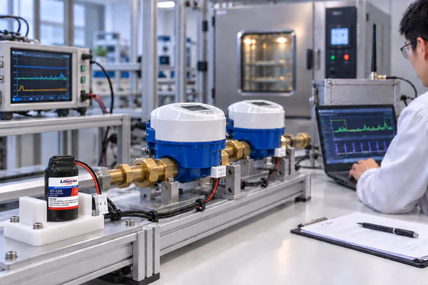
Final validation should use the assembled meter.
Useful conditions include:
new battery + normal network
long-idle / passivated battery + communication
low temperature + weak network
end-of-life battery + NB-IoT event
valve operation + communication
repeated events with limited recovery
Can the complete water meter meet its required service life while maintaining sufficient voltage through every specified operating condition?
OEM Battery-Sizing Input Checklist
| Requirement | Information Needed |
|---|---|
| Sleep | PSM / standby current and duration |
| Measurement | Sensor + MCU waveform |
| NB-IoT | Complete registration / TX / RX / signaling waveform |
| Transmission frequency | Events per day / month |
| Network condition | Normal and weak-coverage behavior |
| Valve | Startup, running current, duration and retries |
| Minimum voltage | Actual meter operating threshold |
| Service life | Required field duration |
| Temperature | Storage, operation and transmission conditions |
| Mechanical space | Available ER / HPC envelope |
| Event sequence | Consecutive pulses and recovery interval |
| Reserve | Required end-of-life margin |
Where LONGSING Fits
LONGSING Website A focuses on primary lithium power for long-life metering and IoT applications.
Relevant internal product and application resources include:
- Li-SOCl₂ Batteries
- IoT Battery Packs
- Hybrid Pulse Capacitors
- HPC1520
- ER26500 + HPC1520
- ER26500 + HPC1550
- Smart Water Meter Application
These pages confirm that Website A already has a strong Li-SOCl₂ / metering / ER + HPC product structure.
The engineering sequence should remain:
Meter Load Profile
↓
Lifetime Charge / Energy Requirement
↓
Candidate ER Capacity
↓
Worst-Case Pulse Waveform
↓
Minimum System Voltage
↓
Standalone ER Validation
↓
HPC Selection if Required
↓
Complete Meter Validation
Conclusion
A reliable NB-IoT water meter battery cannot be selected from nominal capacity alone. The Li-SOCl₂ ER cell should be sized from the meter’s long-term charge and energy requirement, while NB-IoT transmissions and optional valve loads must be checked separately for voltage and pulse-power demand.
If a standalone ER cell provides sufficient lifetime energy but cannot maintain the meter’s required voltage during the worst pulse event, an HPC can provide transient support. The final architecture should then be validated under realistic network, temperature, passivation and end-of-life conditions.
Developing an NB-IoT Smart Water Meter or Utility-Meter Platform?
For a meaningful battery evaluation, provide the complete electrical profile, including sleep current, measurement load, NB-IoT communication waveform, transmission frequency, weak-network behavior, valve load where applicable, service-life requirement, minimum system voltage, temperature profile, available battery space and expected pulse-recovery interval.
These inputs allow the ER-cell energy requirement and HPC pulse-support requirement to be evaluated independently and then validated together against the real meter design.
Frequently Asked Questions About NB-IoT Water Meter Batteries
Click to explore more information about NB-IoT Water Meter Batteries
Q: How do you calculate battery life for an NB-IoT smart water meter?
A: Calculate the charge or energy consumed by sleep, sensing, communication, valve operation and other loads over the required service life. Then include validated allowances for self-discharge, temperature, conversion losses, network retries, usable voltage and reserve. Do not estimate lifetime by simply dividing nominal battery Ah by one instantaneous current value.
Q: Which Li-SOCl₂ cell is suitable for a smart water meter?
A: There is no universal model. ER14505, ER26500 and ER34615 may be candidate sizes depending on lifetime energy, physical dimensions, load profile, temperature and minimum system voltage. The actual selection should follow the meter specification rather than an application label.
Q: Does every NB-IoT water meter need an HPC?
A: No. If the selected standalone Li-SOCl₂ cell provides enough lifetime energy and maintains sufficient voltage during the worst communication, temperature and end-of-life conditions, an HPC may not be necessary.
Q: Why can an NB-IoT water meter reset while the battery still has capacity?
A: The cell may still contain chemical energy but experience enough voltage sag during a communication or valve event to fall below the modem, MCU or system minimum voltage. In that situation, nominal remaining capacity is not fully usable by the meter.
Q: How does poor NB-IoT signal affect water meter battery life?
A: Weak radio conditions can increase connection time, repetitions and retransmissions, raising the energy consumed per communication event. Laboratory lifetime calculations based only on strong coverage may therefore underestimate real field consumption. [3]
Q: How does Li-SOCl₂ passivation affect NB-IoT transmission?
A: Passivation limits unwanted long-term chemical reaction at the lithium surface but can increase initial impedance after extended storage or low-current operation. When a much larger load is suddenly applied, the cell may exhibit temporary voltage delay or voltage sag. [4]
Q: How do you size an HPC for NB-IoT pulse current?
A: Evaluate the complete pulse waveform, including peak current, duration, allowable voltage drop, HPC impedance, effective stored charge, temperature, repeated events and recovery interval. Peak current alone is not enough.
Q: Can LONGSING’s 1 A, 2 A or 3 A ER + HPC ratings be directly applied to a valve load?
A: No. LONGSING publishes those maximum pulse figures under a stated 1-second pulse / 3.0 V termination condition. A different pulse duration, meter minimum voltage, temperature or repetition pattern requires separate validation. [7]
Reference

CR123A, CR17450, and CR14505 The Ultimate CR Li-MnO2 Cylindrical Battery Comparison
Your industrial meter just failed in the field. The replacement costs are mounting. You need a batte

What Makes the Science Behind Lithium Thionyl Chloride Battery So Unique?
Power systems need reliable energy sources. Industrial applications face harsh conditions every day.
Choosing Between Lithium Manganese Dioxide vs Lithium-Ion Batteries
Selecting the wrong chemistry can result in premature field failures, ballooning maintenance costs,