

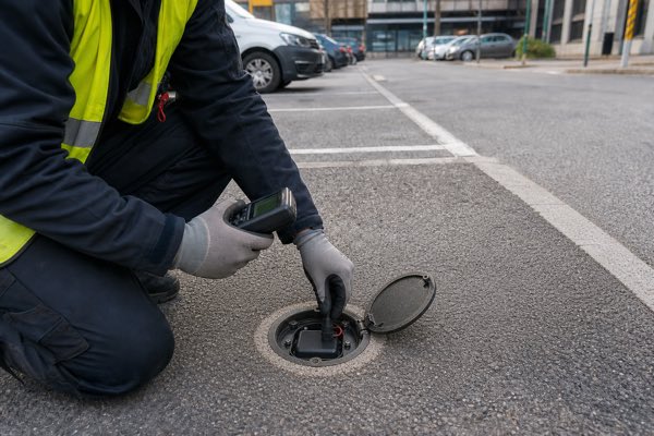
4 Proven Ways for Your Smart Parking Sensor Battery
A parking sensor may consume very little energy on an average day. But once hundreds or thousands of units are installed in streets, parking bays or difficult-to-access infrastructure, replacing batteries becomes a field-maintenance project involving labor, access planning and service cost.
The engineering target is therefore not simply maximum Ah. It is keeping the sensor operational until the planned maintenance interval under its real wireless, temperature and voltage conditions.
A Li-SOCl₂ primary lithium battery is suitable for many long-life smart parking sensors because it combines high stored energy with low self-discharge and a stable nominal voltage. However, the correct smart parking sensor battery depends on sleep current, transmission current, pulse duration, temperature, minimum system voltage and deployment life. If the radio pulse exceeds the ER cell’s practical voltage margin, an ER + HPC pulse-support architecture may be considered.
LoRaWAN itself is designed for battery-powered end devices. In Class A, a device can remain in low-power sleep until its application initiates an uplink, making the communication architecture compatible with long-sleep sensor designs. [2]
Table of Contents
- 1. Why Do Smart Parking Sensors Create a Unique Battery Design Problem?
- 2. How Do Load Profile, Wireless Transmission and Environment Affect Battery Life?
- 3. How Should Engineers Use Li-SOCl₂ and Pulse Support in Parking Sensors?
- 4. What Should OEMs Specify Before Selecting a Smart Parking Sensor Battery?
1. Why Do Smart Parking Sensors Create a Unique Battery Design Problem?
A smart parking sensor battery powers a device that may spend most of its life doing almost nothing electrically—then suddenly wake, sense a vehicle, process data and transmit it wirelessly.
That contrast between very long low-current periods and short active events is what makes battery selection more complicated than simply dividing nominal battery capacity by average current.
Smart parking deployments commonly combine sensing infrastructure with LPWAN communication such as LoRaWAN. Published smart-parking architectures describe sensors collecting parking-space status and transmitting data through LoRaWAN gateways to backend systems. [1]
Battery Replacement Is an Infrastructure Cost
For a consumer device, replacing a battery may take a few minutes.
For a deployed parking sensor, replacement can involve:
- locating the correct sensor;
- accessing a parking bay;
- temporarily interrupting service;
- opening a sealed enclosure;
- replacing and resealing the battery;
- testing communications;
- scheduling technicians;
- coordinating road or parking access.
The important metric is therefore not only:
How much does the battery cost?
It is also:
How much does one field battery replacement cost across the installed sensor network?
As deployment scale increases, maintenance interval becomes part of the economic design of the IoT system.
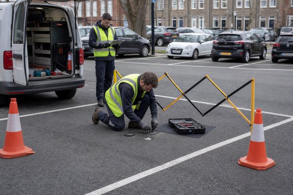
LONGSING’s current Website A Smart City application page specifically lists smart parking as an outdoor, hard-to-reach application for primary lithium and pulse-support solutions.
The Sensor Has Multiple Electrical States
A realistic smart parking power profile can include:
Sleep
↓
sensor electronics at very low standby power
Wake-up
↓
MCU and sensing circuit become active
Measurement
↓
magnetic, radar or other occupancy detection
Processing
↓
data filtering and decision logic
Wireless transmission
↓
LoRaWAN or NB-IoT communication
Receive / network activity
↓
protocol-dependent listening or signaling
Return to sleep
The time spent in each state matters.
A sensor that sleeps efficiently for nearly all of its deployment can have an extremely low average current, but that does not mean every battery capable of supplying the average current will operate the radio successfully.
Average energy demand determines much of lifetime; instantaneous power demand determines whether the device can execute each active event without collapsing below its voltage threshold.
2. How Do Load Profile, Wireless Transmission and Environment Affect Battery Life?
Battery life in a smart parking sensor depends on the entire load profile: sleep current, sensing activity, transmission current, transmission duration, radio frequency, temperature, self-discharge and the device’s minimum operating voltage.
Sleep Current and Transmission Current Are Different Design Problems
A first-pass lifetime estimate often starts with:
Estimated Life ≈ Available Capacity ÷ Average Current
This can be useful for preliminary budgeting, but it is not a complete battery design model.
A better average-current calculation considers the duty cycle:
Iavg ≈ Σ(I × t) / Total Time
That means the engineer should include:
- MCU sleep current;
- sensor standby current;
- sensing events;
- processing time;
- radio TX;
- radio RX;
- network registration or retries;
- periodic diagnostics;
- self-discharge;
- environmental derating;
- end-of-life engineering margin.
Yet even a carefully calculated average current still does not answer:
Can the battery keep the system voltage above the device cut-off during the highest-current event?
That requires looking at the actual current-versus-time waveform.
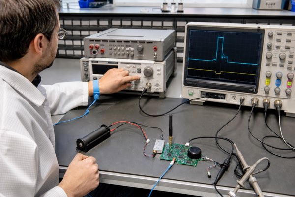
Why LoRaWAN Still Creates Transmission Pulses
LoRaWAN is optimized for battery-powered applications, especially when an end device can remain in low-power sleep and transmit only when needed. Class A is the lowest-power LoRaWAN operating class because the device initiates uplinks and can otherwise remain asleep. LoRaWAN data rate also affects message airtime, creating a trade-off between range and transmission duration.
Low average power, however, does not mean zero radio-current demand.
During an uplink event, the RF section must wake and transmit. The battery therefore sees a waveform more like:
Long sleep
↓
short active sensing
↓
radio transmission
↓
receive windows
↓
sleep again
For a LoRaWAN parking sensor battery, the important inputs include:
- TX power;
- spreading factor / data rate;
- payload size;
- retransmissions;
- transmission interval;
- receive-window activity;
- actual module current profile.
These parameters affect both total energy and peak-load behavior.
NB-IoT Can Create a Much Larger Gap Between Sleep and TX Current
The contrast can be even more obvious in cellular IoT.
For example, u-blox’s SARA-N2 documentation reports a deep-sleep current in the microamp range but much higher current while transmitting; the integration manual specifically warns that the power supply must withstand maximum transmission current even though the module should spend most of its life in deep sleep.
Nordic Semiconductor documents that NB-IoT transmission combines low-power modes with much higher-current TX activity, and that peak current must be distinguished from average modem current. [3]
This is exactly why the following reasoning can fail:
“The sensor averages only a few microamps, so any high-capacity battery will work.”
The radio may require an entirely different power capability from what the average-current figure suggests.
Network Conditions Matter Too
NB-IoT energy consumption is not determined only by the application firmware.
Network parameters can influence:
- TX output power;
- registration activity;
- RRC behavior;
- repetitions;
- paging;
- PSM / eDRX operation.
The GSMA NB-IoT Deployment Guide explains that PSM behavior depends on timers negotiated with the network, so device firmware is not the only factor in long-term energy use. [4]
For battery qualification, engineers should therefore measure the real modem waveform under representative network conditions, rather than relying only on a typical-current number from a module datasheet.
Why Self-Discharge Matters in a Multi-Year Sensor
When the electronic load is very small, battery self-discharge stops being a negligible background term.
If a sensor is expected to remain unattended for years, its battery must lose as little stored energy as practical while sitting at low load.
LONGSING’s current Website A ER product information publishes a self-discharge figure of less than 1% per year at 20°C for its ER-series Li-SOCl₂ cells. This is a LONGSING product specification and should not be generalized to every Li-SOCl₂ cell or every field condition.
Manufacturer cell data likewise shows why low self-discharge and stable voltage response matter in long-duration, low-base-current applications. [5]
Temperature Affects More Than Capacity
Outdoor parking sensors may experience significant seasonal temperature variation.
Temperature can influence:
- available capacity;
- internal resistance;
- voltage under load;
- passivation behavior;
- radio-system demand;
- self-discharge;
- electronics cut-off margin.
A cell that performs comfortably with a fresh battery at room temperature may provide much less voltage margin after long storage at a colder field condition.
Therefore, lifetime verification should not be limited to:
fresh battery + room temperature + nominal load
A more useful validation matrix includes:
- fresh cell;
- after storage / long sleep;
- low temperature;
- elevated temperature;
- partially depleted battery;
- worst radio-transmission event;
- repeated transmissions;
- end-of-life simulation.
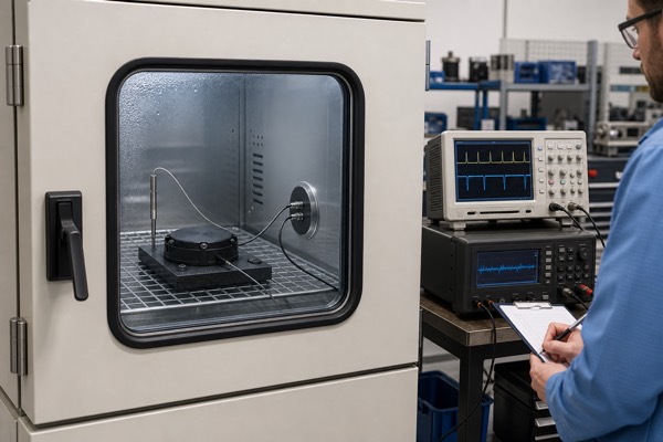
3. How Should Engineers Use Li-SOCl₂ and Pulse Support in Parking Sensors?
Li-SOCl₂ is well suited to many unattended smart parking applications because its bobbin-type ER cells are designed around long-duration, low-current operation. But the correct architecture depends on whether the standalone ER cell can maintain sufficient voltage during the sensor’s actual wireless pulse.
Why Li-SOCl₂ Fits Long-Life IoT Duty Cycles
LONGSING Website A currently publishes ER-series Li-SOCl₂ products with:
- 3.6 V nominal voltage;
- low self-discharge;
- high energy density;
- multiple cylindrical sizes;
- current ratings that vary by model.
For example, current LONGSING published specifications include:
These values are LONGSING’s current published cell specifications, not smart-parking load requirements. [7] A parking-sensor designer should not select ER14505, ER26500 or ER34615 simply because a radio pulse is numerically below a published maximum current. Real voltage margin, pulse duration, temperature, cell age and cut-off voltage still need to be tested.
The practical design logic is:
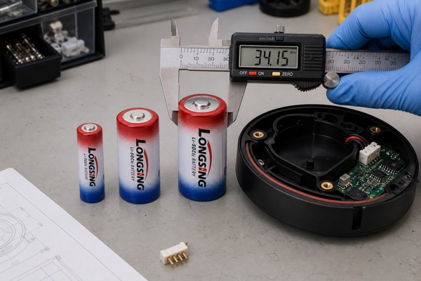
ER cell size primarily answers the energy question.
The radio waveform answers the pulse-power and voltage-margin question.
What Is Passivation in a Li-SOCl₂ Battery?
Passivation is not simply a defect.
During storage or low-current operation, a protective layer develops on the lithium anode. This contributes to the chemistry’s storage characteristics, but it also increases impedance.
When a significant load is suddenly applied after prolonged low-load operation, the terminal voltage can initially dip before recovering as the passive layer changes under discharge.
This is the voltage-delay phenomenon.
Battery technical guidance on temperature and passivation explains that the protective layer supports long storage but can raise impedance and reduce available pulse power after idle periods or under demanding conditions. [6]
The important distinction is:
Passivation helps make long storage possible, but it can complicate the first high-current event after a long idle period.
That is why a parking sensor can have plenty of chemical energy remaining yet still fail to transmit if the load drives terminal voltage below the MCU or modem’s minimum operating voltage.
When Can an ER Cell Alone Be Enough?
An ER-only architecture may be appropriate when:
- average current is low;
- peak current is within practical cell capability;
- pulse duration is manageable;
- the minimum system voltage leaves adequate margin;
- temperature conditions are acceptable;
- passivation-related voltage delay remains within the system tolerance;
- end-of-life testing confirms reliable communications.
This is important:
Not every LoRaWAN or NB-IoT parking sensor needs an HPC.
A low-power LoRa design with modest RF demand and sufficient voltage margin may operate successfully from a standalone ER cell.
The architecture should follow measurements—not a blanket rule.
When Should ER + HPC Be Evaluated?
An ER + HPC pulse-support system becomes worth evaluating when the standalone ER cell has sufficient lifetime energy but insufficient transient voltage margin under the required wireless load.
The basic architecture is:
Sleep / low-load period
↓
ER battery powers background electronics and replenishes the HPC
Wireless transmission
↓
HPC supplies a significant share of transient current
After transmission
↓
ER gradually restores the HPC before the next pulse
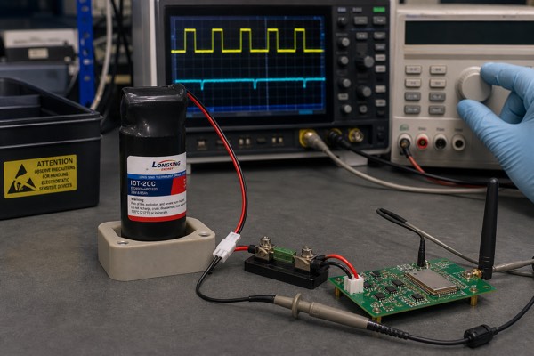
Published electrochemical research on Li/SOCl₂ cells connected in parallel with a capacitor found that the capacitor acts as a high-current buffer and suppresses passivation-related voltage delay during high-rate pulses.
LONGSING’s current HPC documentation describes the same system architecture: the Li-SOCl₂ cell and HPC are connected in parallel, with the HPC carrying much of the external pulse current and the ER cell restoring it during the lower-load interval.
Low-Pulse vs Higher-Pulse Parking Sensor Architecture
| Design Factor | Lower-Pulse Parking Sensor | Higher-Pulse Wireless Parking Sensor | Battery Design Impact |
| Standby load | Very low | Very low | Drives long-term energy budget |
| Wireless event | Modest pulse | Higher current / longer radio event | Determines transient power requirement |
| Minimum system voltage | Comfortable margin | Narrower voltage margin possible | Must verify load-induced voltage drop |
| Transmission frequency | Infrequent | More frequent or retries possible | Affects both energy and HPC recovery |
| Temperature | Moderate conditions | Wider or colder deployment | Can reduce transient voltage margin |
| ER-only architecture | May be sufficient | Must be verified carefully | Depends on actual waveform |
| ER + HPC architecture | May be unnecessary | May provide useful pulse support | Evaluate from pulse energy and voltage margin |
HPC Selection Is Not Based on Peak Current Alone
If pulse support is required, the engineer should provide:
- radio startup current;
- TX current;
- current waveform;
- pulse duration;
- number of consecutive events;
- time between transmissions;
- minimum operating voltage;
- temperature;
- battery state-of-life.
A simplified capacitor relationship is:
ΔV ≈ I × t / C
and an ESR-related instantaneous drop can be approximated as:
ΔV_ESR ≈ I × ESR
These are useful first-order relationships, but an actual ER + HPC system should be verified with the real device load.
LONGSING publishes multiple ER + HPC combinations, including ER14505-, ER26500– and ER34615-based configurations. The published pulse figures use specific test conditions—for example, a 1-second pulse at a 3.0 V termination condition—and must not be treated as universal radio compatibility ratings. [8]
The correct question is not “Which HPC has the largest pulse number?” It is “Which ER + HPC combination keeps this sensor above its minimum operating voltage for its real wireless event under worst-case conditions?”
4. What Should OEMs Specify Before Selecting a Smart Parking Sensor Battery?
An OEM should define the complete electrical, environmental and maintenance requirements before selecting a smart parking sensor battery. This allows the battery supplier to distinguish the energy requirement from the pulse-power requirement.
Electrical Requirements
Provide:
- operating voltage;
- minimum allowable system voltage;
- regulator architecture;
- MCU cut-off voltage;
- sensor current;
- sleep current;
- average current;
- maximum current.
The minimum system voltage is particularly important.
Battery design is not finished when nominal battery voltage is above the electronics specification. The engineer must check:
What is the lowest voltage seen at the electronics during the worst pulse?
Wireless Load Profile
For LoRaWAN, provide:
- radio module;
- TX power;
- data rate / spreading factor;
- transmission interval;
- packet duration;
- receive-window behavior;
- retransmission strategy;
- worst measured radio current.
For NB-IoT, provide:
- modem model;
- network technology;
- PSM / eDRX settings;
- typical TX power;
- maximum TX current;
- network registration behavior;
- active-time profile;
- retries / repetitions;
- representative current waveform.
Do not reduce either radio technology to a single “peak-current” number.
Lifetime and Maintenance Requirements
Define:
- expected deployment life;
- planned maintenance interval;
- acceptable replacement frequency;
- transmissions per day;
- sensing interval;
- diagnostic events;
- firmware behavior.
A theoretical capacity calculation should include engineering margin rather than attempting to consume the cell’s entire nominal rating on paper.
Conservative margin becomes more important as field-access cost rises. A model should account for realistic current waveforms, temperature, self-discharge, regulator losses, battery aging and a defined end-of-life voltage—not only nominal amp-hours.
Environmental and Mechanical Requirements
Provide:
- operating and storage temperature range;
- enclosure sealing strategy;
- expected moisture and condensation exposure;
- shock and vibration conditions;
- battery orientation;
- available dimensions and mass;
- tab, lead-wire and connector requirements;
- installation and replacement procedure.
The cell may have a wide published temperature range, but the complete sensor must still be validated as a system. Wiring resistance, connector resistance, regulator behavior and enclosure temperature can all reduce voltage margin during a wireless event.
Smart Parking Sensor Battery Specification Checklist
| Required Input | What the OEM Should Provide | Why It Matters |
| Operating voltage | Nominal and maximum supply voltage | Defines cell and regulator compatibility |
| Minimum system voltage | MCU, sensor and radio brownout threshold | Sets allowable pulse-induced voltage drop |
| Sleep current | Measured current in the longest standby state | Drives the multi-year energy budget |
| Sensing profile | Current, duration and interval | Adds recurring energy consumption |
| Wireless waveform | Current versus time for LoRaWAN or NB-IoT | Defines pulse-power requirement |
| Transmission behavior | Interval, TX power, airtime, retries and receive windows | Changes both energy and recovery time |
| Temperature range | Normal and worst-case field conditions | Affects capacity, impedance and voltage margin |
| Deployment target | Required life and planned maintenance interval | Defines usable-energy and design-margin goals |
| Battery envelope | Maximum dimensions, mass and connector position | Constrains ER and HPC architecture |
| Validation conditions | Fresh, stored, low-temperature and end-of-life tests | Confirms the design beyond nominal conditions |
Match the Battery Architecture to the Measured Load
A useful selection sequence is:
- calculate the sensor’s lifetime energy requirement from its measured operating states;
- select an ER cell size that fits the usable-energy and mechanical targets;
- verify the standalone cell against the worst transmission waveform;
- evaluate ER + HPC only if pulse voltage margin or recovery behavior is insufficient;
- test the complete battery, wiring, regulator, sensor and radio under representative worst-case conditions.
LONGSING can evaluate standard ER cells, ER + HPC configurations and custom primary lithium battery assemblies, but the application data must come first. For an OEM review, provide the operating voltage, minimum system voltage, average current, peak current, pulse duration, transmission interval, temperature range, expected deployment life and available battery dimensions.
Conclusion
A reliable smart parking sensor battery is designed from the real duty cycle, not from nominal capacity alone. Sleep current and sensing determine much of the long-term energy requirement, while LoRaWAN or NB-IoT events determine transient current and voltage margin. Temperature, self-discharge, passivation, regulator behavior and maintenance targets must be included in the same model.
Li-SOCl₂ ER cells are strong candidates for unattended smart-city sensors because they combine high stored energy, stable nominal voltage and low self-discharge. A standalone ER cell may be sufficient for a lower-pulse design. ER + HPC should be considered only when the measured wireless waveform, minimum system voltage and worst-case conditions show that additional pulse support is useful.
Discuss Your Smart Parking Sensor Battery Requirement
For a technical evaluation, send LONGSING engineers:
- operating voltage and minimum cut-off voltage;
- sleep and average current;
- measured peak-current waveform;
- pulse duration and transmission interval;
- LoRaWAN or NB-IoT module details;
- operating temperature range;
- expected deployment life;
- maximum battery dimensions and connector requirements.
This information allows the battery architecture to be evaluated around the sensor rather than forcing the sensor around a predefined cell.
Frequently Asked Questions About Smart Parking Sensor Batteries
Click to explore more information about smart parking sensor batteries
Q: What battery is used in smart parking sensors?
A: Many long-life parking sensors use a primary lithium battery such as Li-SOCl₂, but the correct choice depends on operating voltage, sleep current, sensing load, wireless pulse, temperature, enclosure space and maintenance target.
Q: Why are Li-SOCl₂ batteries suitable for smart parking sensors?
A: Li-SOCl₂ cells combine high stored energy, a stable nominal voltage and low self-discharge, which suits devices that spend long periods asleep and must operate unattended. Their pulse behavior, passivation and voltage margin still require application testing.
Q: How long can a smart parking sensor battery last?
A: There is no universal service-life figure. Actual life depends on usable battery capacity, sleep current, sensing interval, transmission frequency, retries, temperature, self-discharge, regulator losses, pulse behavior and the system cut-off voltage.
Q: How does LoRaWAN affect parking sensor battery life?
A: LoRaWAN Class A supports long sleep periods, but each uplink still creates a radio event followed by receive windows. TX power, data rate, airtime, packet interval, acknowledgements and retries all influence energy use and pulse demand.
Q: Does NB-IoT require high pulse current from the battery?
A: NB-IoT modems can transition from very low-power modes to substantially higher TX current. The battery should be evaluated with the selected modem’s measured waveform under representative registration, signal-strength, repetition and network conditions.
Q: What is battery passivation in Li-SOCl₂ cells?
A: Passivation is a protective layer that forms on the lithium anode and helps limit self-discharge. It can also raise initial impedance, creating temporary voltage delay when a significant load is applied after storage or extended low-current operation.
Q: When does a smart parking sensor need an HPC?
A: An HPC may be useful when the standalone ER cell cannot maintain adequate voltage during the actual wireless pulse, especially under low-temperature, long-idle or end-of-life conditions. Not every LoRaWAN or NB-IoT parking sensor needs one.
Q: What information is required to select a battery for a smart parking sensor?
A: Provide operating voltage, minimum system voltage, sleep and average current, peak-current waveform, pulse duration, transmission interval, radio module, temperature range, expected deployment life, battery dimensions and connector requirements.
Reference
[4] Review how NB-IoT PSM timers and network behavior affect device energy consumption. ↪
[8] Review the stated test conditions behind LONGSING ER + HPC pulse-support specifications. ↪

Types of Battery: A Guide to LiSoCl₂ Vs LiMnO₂
The need for reliable and long-lasting energy in smart metering drives the comparison between these

What is the difference between industrial batteries and regular batteries?
Industrial batteries and regular batteries differ mainly in their construction, capacity, and intend
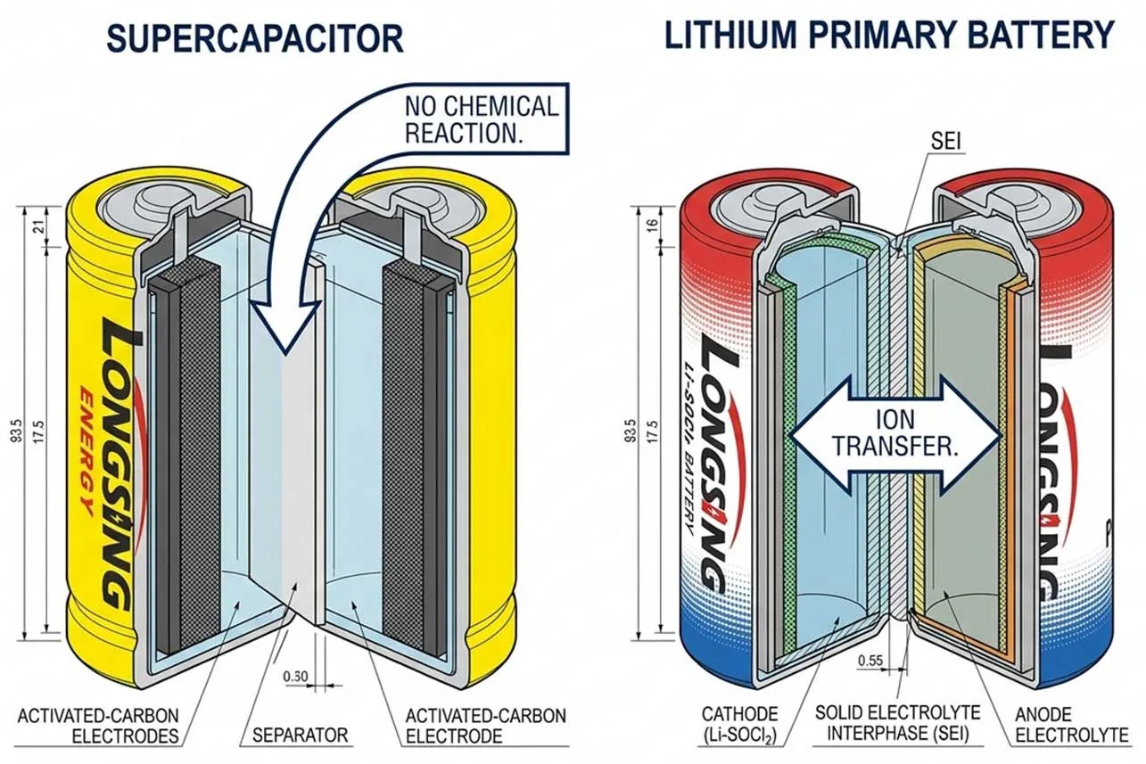
Are supercapacitors safer than batteries?
Supercapacitors are inherently safer than batteries due to electrostatic storage, yet batteries rema