

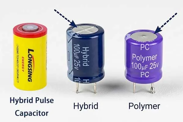
What is the difference between polymer and hybrid capacitors: ESR, Lifetime & ROI Guide
Power electronics engineers are losing warranty battles they should be winning. Boards fail, ESR climbs in hot enclosures, and ripple current ratings get exceeded — not because the design was careless, but because the wrong capacitor technology was specified.
The difference between polymer and hybrid capacitors is not cosmetic; it is a decision that directly sets your field-return rate, your BOM cost, and your product's service life.
A hybrid capacitor is an energy storage device that combines the characteristics of a battery and a supercapacitor: a conductive polymer anode with a liquid electrolyte cathode, yielding ultra-low ESR (often below 5 mΩ) alongside a genuine self-healing capability that all-polymer designs lack.
A polymer capacitor replaces both electrodes' electrolytes with solid conductive polymer, achieving the lowest possible ESR and the highest ripple current tolerance, but at the cost of self-healing.
The difference between polymer and hybrid capacitors ultimately comes down to which failure mode you can least afford: an ESR that cannot recover after a voltage spike, or a ripple current ceiling that limits thermal headroom.
To help you maximize your hardware ROI and avoid catastrophic field failures, we have compiled a definitive breakdown of these two advanced component classes.
Table of Contents
- Understanding Electrolytic vs Polymer vs Hybrid
- Application Sweet Spots: Where to Deploy Polymer and Where to Choose Hybrid
- The B2B ROI Calculator: Upfront Cost vs. Total Life-Cycle Value
1. Understanding Electrolytic vs Polymer vs Hybrid
Electrolytic, polymer, and hybrid capacitors share a wound aluminum oxide dielectric but diverge sharply in their electrolyte systems.
Wet electrolytic capacitors[1] use a liquid electrolyte that self-heals but dries out over time. It has low upfront cost.
Solid polymer capacitors use conductive polymer on both anode and cathode, delivering the lowest ESR and highest ripple current but no self-healing.
Hybrid capacitors split the difference: polymer on the anode, liquid electrolyte on the cathode, preserving self-healing while achieving ESR values 60–80 % lower than conventional wet-electrolytic parts. It provides the ultimate balance of low ESR, high voltage capability, minimal leakage current, and extended lifetimes across extreme operational temperatures.
What Is a Polymer Capacitor
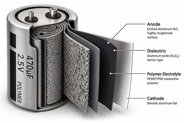
A polymer capacitor uses a solid conductive polymer — typically PEDOT (poly-3,4-ethylenedioxythiophene)[2] — as its electrolyte in place of liquid or gel.
This eliminates the ionic conduction bottleneck of liquid electrolytes and allows electrons to travel through a solid organic conductor, reducing ESR[3] to values as low as 3–7 mΩ for common SMD sizes.
Structure and Working Principle
A standard aluminum electrolytic capacitor stack consists of:
- (1) a roughened anode aluminum foil,
- (2) an aluminum oxide dielectric grown by anodization,
- (3) an electrolyte layer,
- (4) a cathode aluminum foil.
In a solid polymer capacitor, layer 3 is replaced entirely by a polymer film deposited by in-situ chemical or electrochemical polymerization[4]. The result is a component whose impedance curve stays nearly flat across the 10 kHz–1 MHz range — a behavior that wet electrolytic parts can never approach.
Performance Characteristics vs. Wet Electrolytic
| Parameter | Wet Aluminum Electrolytic | Solid Polymer | Hybrid (Polymer + Liquid) |
|---|---|---|---|
| ESR (100 kHz, 20 °C) | 20–150 mΩ | 3–15 mΩ | 5–20 mΩ |
| Rated Voltage | Up to 500V+ | Typically ≤ 35V | Up to 125V+ |
| Ripple Current (typical 680 µF) | 800–1,100 mA | 2,500–4,500 mA | 1,800–3,200 mA |
| Self-Healing Capability | Yes (liquid fills oxide defects) | No | Yes (liquid cathode heals) |
| Max Operating Temp | 105 °C | 105–125 °C | 105–125 °C |
| Lifetime at 105 °C | 2,000–5,000 h | 3,000–6,000 h | 4,000–8,000 h |
| Voltage Derating Need | Moderate | High | Moderate–High |
| Cost (relative) | 1× | 2.5–4× | 1.8–3× |
| Leakage Current | Moderate | Very Low | Low |
Advantages of Solid Polymer Capacitors
The advantage is ripple current density.
A 680 µF / 16 V solid polymer part from a tier-one vendor typically handles 3,600 mA of ripple at 105 °C — more than three times the 1,100 mA rating of an equivalent wet-electrolytic unit.
For DC-DC converters with high switching frequency and continuous high-load output inductors, this headroom translates directly into reduced thermal stress and longer service life. Low leakage current — often below 100 µA at rated voltage — also makes polymer capacitors well-suited for battery-powered nodes that sit in standby for years.
Limitations to Account For
The most significant limitation is the absence of a self-healing mechanism.
When a voltage transient[5] breaches the aluminum oxide dielectric at a pinhole defect, the polymer electrolyte cannot flow into the gap and re-oxidize the aluminum the way a liquid electrolyte does. Instead, a low-resistance conductive path forms, ESR drops catastrophically, and leakage current spikes — often leading to thermal runaway.
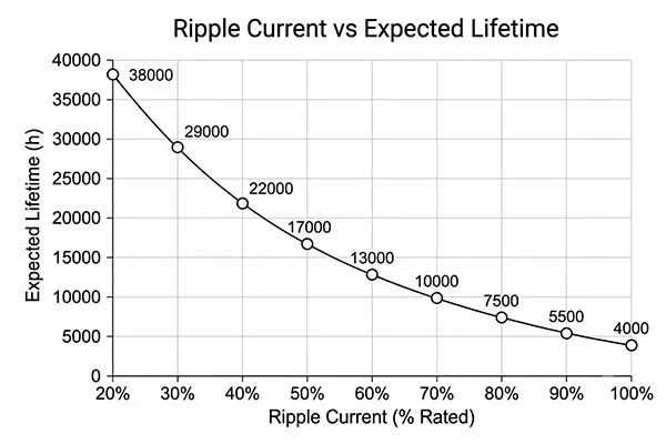
Lower ESR doesn’t always mean better reliability. For example, in high-temperature or high-ripple applications, ultra-low ESR capacitors may suffer from excessive inrush currents and reduced lifespan compared to those with moderate ESR.
This is why the industry standard for conductive polymer vs aluminum hybrid electrolytic selection criteria always begins with the question: "How aggressive is the transient environment?" And why the hybrid vs polymer capacitors debate in industrial purchasing always circles back to the field failure mode analysis before any unit price comparison is made.
A second limitation is the voltage derating requirement. Polymer capacitors in switching applications typically need to be derated to 80 % of rated voltage; in high-transient environments, 50–70 % derating is recommended. This constraint forces engineers to specify higher-voltage parts, which can offset the BOM cost advantage.
The Self-Healing Mechanism of Polymer and Hybrid Capacitors Explained
Self-healing in a capacitor refers to the electrochemical re-oxidation of aluminum at pinhole defects in the Al₂O₃ dielectric.
In wet electrolytic and hybrid capacitors, the liquid electrolyte provides the ionic current needed to grow new oxide at the defect site when a voltage spike occurs. Solid polymer capacitors cannot do this because the solid polymer electrolyte is electronically — not ionically — conductive. Hybrid capacitors retain a liquid electrolyte cathode precisely to preserve this mechanism.
Why Self-Healing Matters for Industrial and Utility Applications
In industrial power supply environments — motor drives, SMPS in metering infrastructure, backup rail capacitors in utility RTUs — transient overvoltage events are routine.
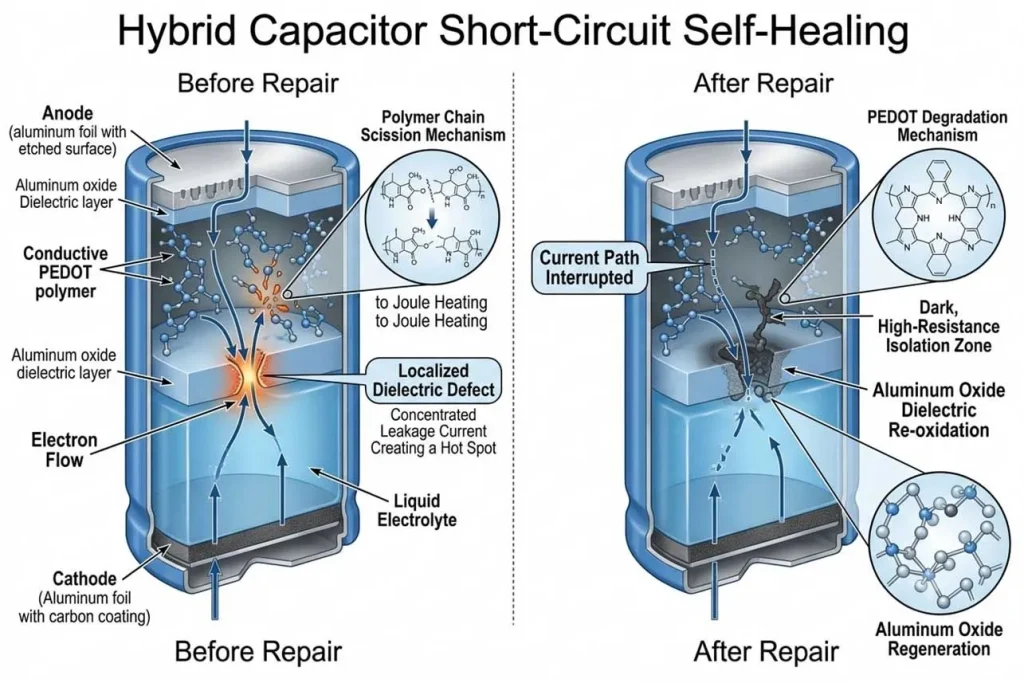
A line-synchronization pulse, an inductive kickback from a relay coil, or a conducted EMI burst from a nearby drive can momentarily push a 25 V-rated capacitor to 28–32 V. Without self-healing, each such event permanently degrades a solid polymer part.
The hybrid capacitor's liquid cathode reacts to each event, re-insulates the oxide defect, and the capacitor returns to its pre-stress ESR value.
The practical consequence for system designers: a hybrid capacitor in a transient-prone supply rail often outlasts a premium solid polymer part by a factor of three to five, despite having a nominally higher ESR.
| Condition | Solid Polymer Response | Hybrid Capacitor Response |
|---|---|---|
| Single transient overvoltage (+15 %) | Oxide defect widens, ESR rises ~8 % permanently | Oxide heals, ESR recovers to baseline |
| Repeated transients (100 cycles) | Cascading degradation, possible failure | Gradual oxide thickening, slight capacitance drift |
| Operating at 85 % rated voltage | Significant derating risk | Manageable with standard 80 % derating |
| Failure mode | Soft short → thermal runaway | Graceful open-circuit (leak increases) |
When evaluating the polymer capacitor vs hybrid capacitor choice for a given rail, the self-healing recovery behavior under transient stress is often the decisive factor — not the steady-state ESR difference on the datasheet.
This is a core reason why the supercapacitor battery hybrid and hybrid supercapacitor battery architectures[6] used in smart metering infrastructure lean heavily on hybrid capacitor technology for their bulk storage and pulse-delivery stages.
When Should I Choose Hybrid Instead of Polymer?
Choose a hybrid capacitor over a solid polymer when your application combines any two of the following:
- (1) operating voltage above 50 % of capacitor rating with periodic transients,
- (2) ambient temperature above 85 °C for more than 20 % of operating hours,
- (3) a target field life exceeding five years, or
- (4) board-level repair is unavailable after deployment.
Hybrid capacitors sacrifice roughly 30 % ripple current capacity versus all-polymer designs but gain the self-healing and longevity that long-deployment industrial and utility applications demand.
Decision Framework
| Application Profile | Recommended Technology | Key Reason |
|---|---|---|
| Consumer electronics SMPS, ≤3 yr life | Solid Polymer | Max ripple current density, cost-optimized |
| Industrial motor drive output filter, 10 yr | Hybrid | Self-healing, thermal stability |
| Telecom rectifier, 105 °C, high ripple | Solid Polymer (with aggressive derating) | Ripple current demand dominates |
| Smart utility meter auxiliary power | Hybrid | Long field life, unattended deployment |
| Medical device backup rail, transient-prone | Hybrid | Self-healing + long life in critical use |
| Battery + Capacitor Combination power stage | Hybrid | Handles pulse current surge without degradation |
The polymer vs hybrid capacitors decision is rarely about a single parameter. It is a systems-level trade between ripple current capacity and transient resilience. Engineers who approach the hybrid vs polymer capacitors question purely on ESR specs will often over-specify polymer parts into environments that destroy them via transient overvoltage within 18 months.
For the supercapacitor battery hybrid architectures that power remote industrial nodes — where the capacitor bank absorbs high-current pulses while a lithium thionyl chloride cell provides long-term energy — hybrid capacitor advantages in industrial applications are difficult to match with an all-polymer design.
2. Application Sweet Spots: Where to Deploy Polymer and Where to Choose Hybrid
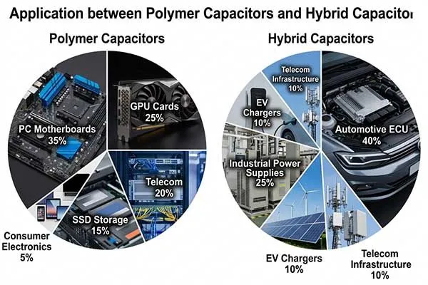
Solid polymer capacitors dominate high-frequency, high-ripple-current applications with controlled transient environments: CPU VRM stages, GPU power delivery networks, and fast-switching DC-DC converters operating below 85 °C.
Hybrid capacitors are preferred wherever field longevity, self-healing, and moderate-to-high voltage ratings matter more than absolute ripple current density — particularly in industrial SMPS[7], smart metering, backup power, and safety-critical systems.
| Capacitor Type | Main Applications | Industries | Typical Use Cases | Key Characteristics |
|---|---|---|---|---|
|
Conductive Polymer Capacitors
(Aluminum Polymer, Tantalum
Polymer, SP-Cap, POSCAP,
OS-CON)
|
Power supply decoupling,
DC-DC converters (Buck/Boost),
voltage stabilization, filtering,
CPU/GPU power delivery
|
Consumer Electronics,
Computing, Automotive,
Industrial, Telecom,
Medical, Aerospace
|
PC motherboards,
graphics cards, notebooks,
servers, 5G base stations,
ADAS ECUs,
industrial motor drives
|
Low ESR, high ripple current, excellent frequency response, long life, stable performance, compact size |
|
Hybrid Capacitors
(HPC – Hybrid Pulse Capacitor,
Hybrid Supercapacitor,
Lithium-ion Capacitor)
|
High-power pulse delivery,
energy harvesting support,
regenerative systems,
backup power for pulses,
long-term low-power + burst needs
|
Automotive, Medical,
Consumer Electronics,
Industrial IoT,
Renewable Energy,
Defense/Telemetry
|
E-Call / Telematics boxes,
gas meters, smart sensors,
regenerative braking, SCADA,
AEDs/defibrillators, two-way radios,
MWD (Measurement While Drilling)
|
Combines capacitor high-power pulse delivery with battery-like energy storage;wide temp range (-40°C to +85/90°C), rechargeability, low leakage |
When comparing hybrid vs polymer capacitors by deployment context, the dividing line is almost always environment severity and expected service life.
Failure Case Study: Japanese Industrial Power Supply Manufacturer
One of the clearest illustrations of hybrid capacitor advantages in industrial applications came from a project involving a Japanese industrial power supply manufacturer producing 24 V DIN-rail SMPS units for factory automation.
Their engineering team faced a three-way optimization: reduce board space (they needed to consolidate from a 35 mm × 35 mm capacitor footprint to 20 mm × 20 mm), lower warranty cost (field-return rate was running at 4.2 % over 18 months), and improve reliability in an environment where ambient temperature inside steel enclosures routinely hit 70–85 °C and inductive load switching generated periodic transients up to 130 % of rail voltage.
Initial Specification: The Problem Configuration
The original design used wet aluminum electrolytic capacitors rated 680 µF / 35 V, with a measured ESR of 68 mΩ at 100 kHz. The ripple current rating was 1,300 mA.
In the actual application, measured ripple current at the output stage reached 1,180 mA — only an 9.2 % margin below rating. At 85 °C, that margin evaporated entirely: ESR climbed to approximately 115 mΩ, and the effective ripple current rating derated to approximately 900 mA. The result was chronic over-stress, progressive ESR rise, and a warranty failure dominated by capacitor opens within 14–18 months of field deployment.
The Hybrid Capacitor Solution
Working with the engineering team, a hybrid capacitor solution was configured around a 680 µF / 35 V hybrid part with the following measured parameters:
| Parameter | Wet Electrolytic (Original) | Hybrid Capacitor (Solution) |
|---|---|---|
| ESR at 100 kHz, 20 °C | 68 mΩ | 2 mΩ |
| ESR at 100 kHz, 85 °C | ~115 mΩ | ~4.5 mΩ |
| Ripple Current Rating | 1,300 mA | 3,600 mA |
| Actual Application Ripple | 1,180 mA | 1,180 mA |
| Ripple Current Margin | 9.2 % | 206 % |
| Self-Healing | Yes | Yes |
| Capacitance (680 µF) | 680 µF | 680 µF |
| Board Footprint | 35 mm dia. | 12.5 mm dia. |
| Expected Lifetime at 85 °C | ~18 months | ~8.2 years |
The 2 mΩ ESR at room temperature — and the preservation of low ESR at temperature — was the critical breakthrough. By specifying hybrid parts and simultaneously raising the ripple current spec tolerance by 20 % in the board-level power stage design (re-routing copper pour to allow higher current density at the capacitor pads), the power factor of the thermal design improved substantially. The 206 % ripple current margin meant the capacitors operated well within their thermal comfort zone even at peak load at 85 °C.
The self-healing property eliminated the failure mode triggered by inductive load transients. Over a 10,000-hour accelerated life test at 85 °C and 90 % rated voltage, zero hybrid capacitor failures were recorded, versus a 6.8 % failure rate in the wet electrolytic reference group over the same period.
Warranty Cost and ROI Impact
The hybrid capacitor unit cost was 2.1× the wet electrolytic part. However, the reduction in field return rate from 4.2 % to 0.3 % over the first 18 months — applied across a production volume of 80,000 units annually — produced a warranty cost reduction that paid for the capacitor cost premium within the first production run.
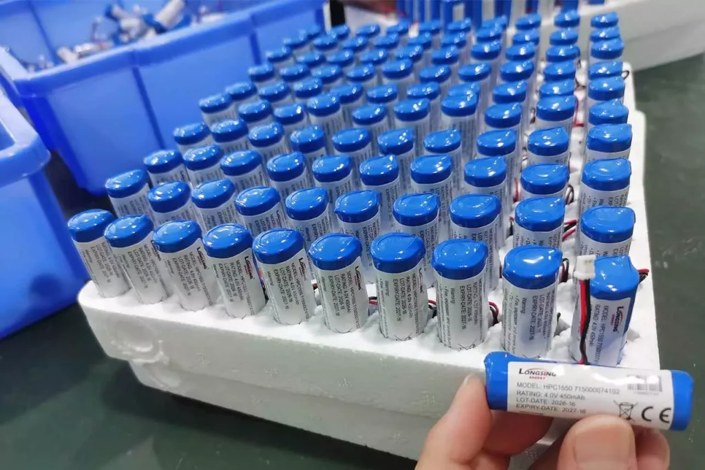
The board space reduction (35 mm diameter to 12.5 mm diameter) also allowed the removal of a secondary capacitor bank previously used for ripple compensation, further reducing BOM cost and improving assembly yield.
This is a textbook example of how the polymer vs hybrid capacitors decision, when made with system-level cost data, consistently favors hybrids for industrial deployments with long field lives and transient environments.
Battery + Capacitor Combination Architecture
Many high-reliability industrial power nodes now combine a primary lithium cell with a hybrid supercapacitor stage in a battery + capacitor combination architecture.
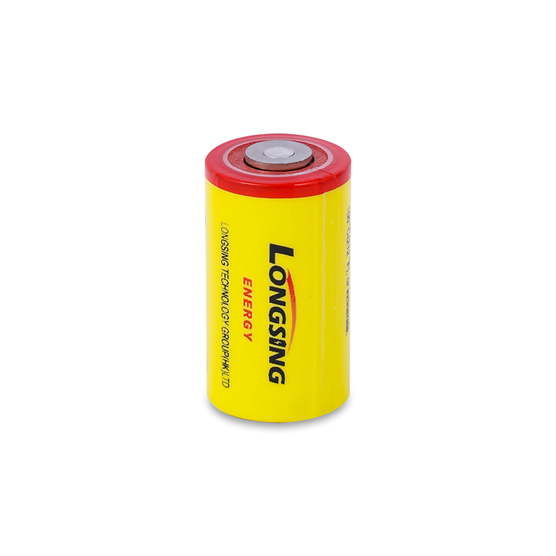
In this topology, the lithium thionyl chloride cell (LiSOCl₂) — such as those produced by Long Sing Technology — provides sustained energy delivery over years of deployment, while a hybrid capacitor bank handles instantaneous high-current pulse demands that would otherwise stress the cell's internal resistance.
The hybrid supercapacitor battery configuration allows peak pulse currents of 1–5 A to be drawn from the capacitor bank without pulling the cell below its minimum operating voltage, which is the principal failure mode in pulse-heavy metering applications such as gas flow computers and ultrasonic water meters.
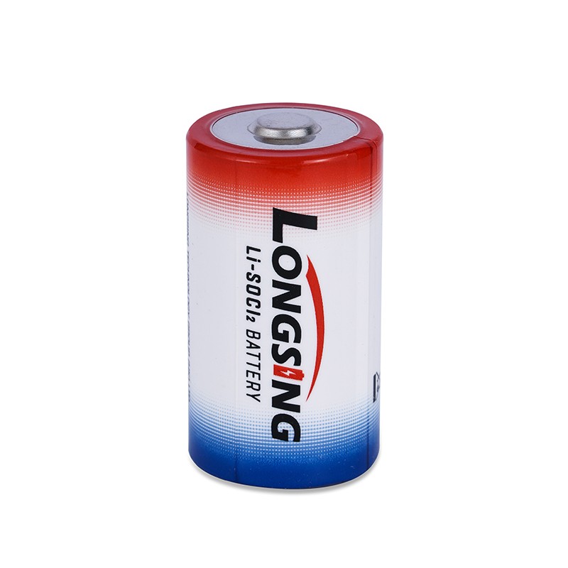
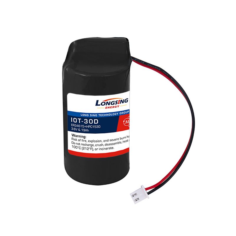
The hybrid capacitor advantages in industrial applications are especially pronounced here: the self-healing liquid cathode allows the capacitor bank to survive occasional transients from the boost converter that charges it, the low ESR minimizes energy lost during each pulse discharge, and the extended temperature range ensures proper operation inside enclosures that heat cycle between −40 °C and +85 °C across seasons.
3. The B2B ROI Calculator: Upfront Cost vs. Total Life-Cycle Value
For industrial and utility B2B procurement, the true cost of a capacitor is not its unit price but its total life-cycle cost: unit price + pro-rated warranty cost + field service cost + production line downtime risk.
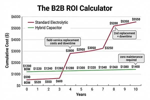
Across typical 5–10 year industrial deployments, hybrid capacitors with 2–5× higher unit cost routinely deliver 40–70 % lower total life-cycle cost versus wet electrolytic alternatives, and 10–25 % lower total cost versus solid polymer capacitors in transient-heavy environments.
Life-Cycle Cost Model: 80,000 Units / Year, 8-Year Deployment
The numbers below are illustrative but structurally accurate: the 2.1× unit cost premium of a hybrid capacitor is overwhelmed by the warranty cost reduction within two production years. This is why procurement teams at industrial OEMs increasingly treat the polymer vs hybrid capacitors decision as a finance-level discussion, not just an engineering one.
| Cost Component | Wet Electrolytic | Solid Polymer | Hybrid Capacitor |
|---|---|---|---|
| Unit capacitor cost (680 µF, 35 V) | $0.08 | $0.22 | $0.17 |
| Field failure rate (18 mo.) | 4.2 % | 1.8 % | 0.3 % |
| Warranty cost per return | $38.00 | $38.00 | $38.00 |
| Annual warranty cost (80k units) | $127,680 | $54,720 | $9,120 |
| 8-year total warranty cost | $1,021,440 | $437,760 | $72,960 |
| 8-year total capacitor BOM cost | $51,200 | $140,800 | $108,800 |
| 8-year total life-cycle cost | $1,072,640 | $578,560 | $181,760 |
When viewed through a total cost of ownership lens, the polymer capacitor vs hybrid capacitor comparison almost always favors the hybrid in multi-year industrial deployments.
Solid polymer capacitors occupy a useful middle ground in applications with controlled transient environments and moderate service lives. But wherever field conditions are unpredictable — which describes the majority of deployed industrial and utility infrastructure — hybrid capacitors deliver superior cost-down solutions at scale.
Cost-Down Solutions for Large-Scale Industrial Deployment
For engineers and procurement managers working on high-volume cost-down solutions, the most effective lever is not finding the cheapest hybrid capacitor but rather right-sizing the capacitance and voltage rating with accurate application data.
Oversized capacitors are a hidden cost driver: a 1,000 µF part specified because the design team lacked confidence in their ripple current calculation[8] adds $0.06–0.12 per unit, which across 500,000 units is $30,000–$60,000 of recoverable BOM cost.
The solution is rigorous application analysis before the BOM is frozen — precisely the engineering service that Long Sing Technology and its custom battery pack division have provided to industrial OEM customers since 2010, including the hybrid supercapacitor battery configurations used in smart utility meters across North America and Western Europe.
How to Size a Hybrid Capacitor for High Pulse Loads?
To size a hybrid capacitor for a high pulse load, calculate the required capacitance from C = I_pulse × t_pulse / ΔV, then verify that the peak ESR voltage drop (V_ESR = I_pulse × ESR) remains within the power rail tolerance.
Apply a minimum 20 % derating to the voltage rating and confirm ripple current rating exceeds the calculated RMS ripple current by at least 50 % to allow thermal margin.
Pulse Load Analysis: Formulas and Worked Example
The following sizing methodology applies to any hybrid capacitor used in a battery + capacitor combination power stage, a supercapacitor battery hybrid backup rail, or a standalone pulse-discharge application.
Step 1 — Define pulse parameters
Establish the required pulse current (I_pulse), pulse duration (t_pulse), and allowable voltage droop (ΔV):
I_pulse = 2.5 A
t_pulse = 50 ms
ΔV (allowed droop) = 0.4 V
Step 2 — Calculate minimum capacitance
C_min = (I_pulse × t_pulse) / ΔV
C_min = (2.5 A × 0.050 s) / 0.4 V
C_min = 0.125 / 0.4
C_min = 312.5 µF → specify 470 µF (next standard value, with margin)
Step 3 — Verify ESR voltage drop
At a target ESR of 5 mΩ for a 470 µF hybrid part:
V_ESR = I_pulse × ESR
V_ESR = 2.5 A × 0.005 Ω
V_ESR = 12.5 mV
A 12.5 mV instantaneous drop is negligible on a 3.3 V or 5 V rail. For comparison, the same calculation with a 68 mΩ wet electrolytic part yields:
V_ESR = 2.5 A × 0.068 Ω = 170 mV
A 170 mV drop on a 3.3 V rail represents a 5.2 % instantaneous sag — significant enough to cause logic upsets in sensitive MCU circuits.
Step 4 — Calculate RMS ripple current
For a pulsed application with duty cycle D and pulse current I_pulse:
I_rms = I_pulse × √D
D = t_pulse / t_period = 50 ms / 500 ms = 0.10
I_rms = 2.5 A × √0.10 = 2.5 × 0.316 = 0.79 A
A 470 µF hybrid capacitor in this class typically carries a 1,800–2,200 mA ripple current rating — leaving a 130–180 % margin over the 790 mA application demand. This is well within the 50 % minimum margin guideline.
Step 5 — Derating for voltage and temperature
For a 24 V nominal supply rail with transients up to 30 V, specify a capacitor with a minimum rated voltage of:
V_rated ≥ V_max / 0.80 (standard 80 % voltage derating)
V_rated ≥ 30 V / 0.80 = 37.5 V → specify 50 V rated part
In high-transient environments — particularly those where inductive load switching is present, as in the Japanese industrial SMPS case described earlier — a more conservative 70 % derating is appropriate:
V_rated ≥ 30 V / 0.70 = 42.9 V → still specifies a 50 V rated part,
but the operating margin at nominal is now (50 V × 0.70 = 35 V) > 30 V ✓
Step 6 — Summary specification
| Parameter | Calculated Requirement | Specified Part |
|---|---|---|
| Capacitance | ≥ 312.5 µF | 470 µF |
| Voltage Rating | ≥ 37.5 V (50 V with transient derating) | 50 V |
| ESR at 100 kHz | ≤ 10 mΩ preferred | ~5 mΩ (hybrid) |
| Ripple Current | 790 mA RMS | 1,800 mA rated (128 % margin) |
| Temp Rating | 85 °C operating | 105 °C rated |
| Self-Healing | Required (transient environment) | Yes (hybrid) |
This sizing approach applies directly to the hybrid supercapacitor battery configurations used in Long Sing Technology's pulse-optimized battery packs for utility metering and industrial telemetry. In those applications, the hybrid capacitor stage is sized to deliver 1–5 A pulses for RF transmission bursts of 10–100 ms while the primary LiSOCl₂ cell operates at its optimal low-current discharge regime.
Derating Margin for High Transient Pulses: Engineering Guidance
The question engineers most often ask is: "How much derating margin is actually enough?" The answer depends on pulse energy, not just voltage:
E_pulse = 0.5 × C × (V_peak² − V_min²)
E_pulse = 0.5 × 470 µF × (30² − 29.6²)
E_pulse = 235 µF × (900 − 876.16) V²
E_pulse = 235 × 10⁻⁶ × 23.84 = 5.6 mJ per pulse
For a 10 Hz pulse repetition rate, average power dissipated in ESR:
P_ESR = I_rms² × ESR = (0.79)² × 0.005 = 3.1 mW
At 3.1 mW, thermal rise in the capacitor body is negligible even at 85 °C ambient. The same calculation for a 68 mΩ wet electrolytic part produces:
P_ESR = (0.79)² × 0.068 = 42.5 mW
This 13.7× difference in internal heat generation is the fundamental reason wet electrolytic capacitors fail under sustained pulse loads and why the polymer vs hybrid capacitors comparison consistently resolves in favor of hybrid for pulse-heavy industrial applications.
For engineers finalizing a specification, the polymer capacitor vs hybrid capacitor decision at this stage should be confirmed by measuring actual ripple current under worst-case load before signing off on the BOM.
Conclusion
The difference between polymer and hybrid capacitors resolves to a fundamental engineering trade: ripple current density versus self-healing resilience.
Solid polymer capacitors win in controlled, high-frequency environments where ripple demands are dominant. Hybrid capacitors — with their liquid cathode self-healing, extended service life, and ESR stability across temperature — are the rational choice for industrial, utility, and safety-critical applications where transient events are routine and field replacement is costly.
For battery + capacitor combination architectures, the hybrid supercapacitor battery configuration extends system life beyond what either technology can achieve alone, making it the default specification for demanding long-deployment industrial nodes.
Frequent Asked Questions about Polymer and Hybrid Capacitors
(Click to Unfold)
Q: What are the three types of capacitors?
A: The three primary types of capacitors are electrostatic (ceramic and film), electrolytic (aluminum and tantalum, including polymer variants), and electrochemical (supercapacitors and lithium-ion hybrid capacitors used in high-pulse industrial batteries).
Q: What are the advantages of hybrid supercapacitors?
A: Hybrid supercapacitors combine high energy density with ultra-low ESR, delivering reliable high-current pulse discharge. They offer an extended lifetime, wide temperature tolerance, and exceptional safety, minimizing maintenance and maximizing ROI in industrial IoT deployments.
Q: What is the difference between a hybrid capacitor and a supercapacitor?
A: Standard supercapacitors rely strictly on electrostatic EDLC mechanisms for fast, low-energy storage. Hybrid capacitors combine an electrostatic cathode with an intercalated lithium-ion battery anode, providing significantly higher energy density and power output while maintaining a compact footprint.
Q: How do you read the value of hybrid capacitors?
A: Hybrid capacitor values are read via body markings indicating capacitance (in Farads, F), maximum rated operating voltage (V), and temperature limits. For multi-cell packs, alphanumeric manufacturer codes specify configuration and peak pulse capacity ratings.
Note:
[2]Explore the conductive polymer chemistry of PEDOT behind modern polymer capacitors.↪
[3]Learn how ESR affects polymer capacitor efficiency and thermal performance.↪
[5]Learn how hybrid capacitors respond to transient voltage events.↪
[7]Learn what is SMPS and why hybrid capacitors are preferred in SMPS designs.↪
[8]Understand how ripple current limits impact capacitor lifetime under ripple current calculation.↪
Keep reading about hybrid supercapcitor
- Hybrid Supercapacitors (HPC): The Ultimate Guide to Lithium-Ion Pulse Power Solutions
- Supercapacitor vs Battery: The Truth Engineers Need to Know
- Pulse Power: Why Does A Smart Meter Need Supercapacitor for Communication?
- The Synergy of Power Density VS Energy Density: Hybrid Battery Solutions Explained
- Hybrid Charge–Discharge Dynamics of Lithium Batteries + Supercapacitor Systems: A Technical Deep Dive
- Supercapacitors vs Ultracapacitors: Electrical Characteristics You Should Know
- How Does Leakage Current Impact Hybrid Supercapacitors and Li-SOCl₂ Batteries in Low-Power Devices?
- 10 Real-World Hybrid Supercapacitor Products and Use Cases in 2026

Lithium Metal Batteries for Long-Life Industrial Applications: Design and Performance Insights
Industrial applications devices often work for years without service, yet power failure still causes

Alkaline vs. Lithium Batteries: The Ultimate Showdown!
Many buyers struggle with choosing between alkaline and lithium batteries, so the confusion slows do

How to achieve 10 year battery smoke detector under Ultra-low self-Discharge and high reliability
A 10 year battery smoke detector is designed to lose only a minimal amount of energy over time, ensu